
19
S-PARK
- rev.1.1_06_2020
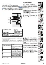
5.3.7
U. Maintenance
U.1 Overall cycles performed
This feature allows to display the overall cycles performed.
No possibility of reset.
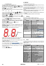
Cycles are displayed 2 by 2 figures:
Ex.:
if the barrier totally performed 823.605 cycles, the screen will
read:
00. 82 36 0.5.
If you wish to scroll figures just press key
.
U.2 Cycles performed since last maintenance service
This feature allows to display the overall cycles performed since last
maintenance service.
Cycles can be reset when a maintenance service has been carried
out (if U.3 is updated and set up).
If you wish to reset press and together holding for 3 seconds:
display will flash “
” to confirm reset successfully completed
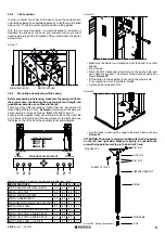
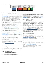
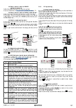
P.4 LED signalling strip (optional)
Boom can be fitted with a RGB led strip that makes the operation more
visible.
The LED strip can be adjusted in 4 different signalling modes when
boom is in closing position.
Refer to be below table:
P.4
Signalling mode when boom in closing position
0
OFF
1
Lit (red light); flashing if battery powered
2 (default) Lit (red light).
3
Flashing (red light)
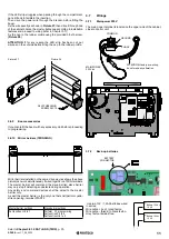
P.5 Light sensor
It is possible to wire a light sensor or daily/weekly timer to switch
the LED signalling strip OFF during day hours.
There are two possible configurations:
• Wiring the N.O. contacts of the sensor/timer in series to COMMON
(terminal BOOM+24)
• Wiring the N.O. contacts of the sensor/timer between GND
and STRT2 or LD, setting
P.5
accordingly; in this case the wired
terminal looses its original function.
P.5
Light sensor possible configurations
0 (default)
No light sensor is wired to STRT2 or LD.
1
Light sensor is wired between STRT2 and COM.
START2 no longer works as pedestrian contact.
2
Light sensor is wired between LD and GND.
LD no longer works as Loop detector.
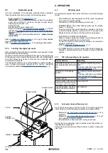
P.6 Cabinet’s safety switch
The barrier may develop extremely dangerous circumstances during
operation.
That’s why if cabinet is opened the barrier immediately stops working
(just figure out if accidentally a radio start command is given, how
dangerous it could be).
However barrier can be managed in “dead man” mode using on
board keys.
P.6
safety function may be switched OFF setting
P.6
to 0 position; by
default
P.6
is
ON (P.6=1)
.
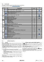
U.3 Maintenance countdown
This feature allows to set the number of cycles till next maintenance
service (starting from a minimum of 1000 cycles and so on).
U.3
will accordingly and automatically update
U.1
and
U.2
if activated,
at every closing operation.
It is also possible to warn the end user that maintenance service is
needed.
To set this function, set parameter
U.4
.
U.4 Maintenance recall
As previously explained in parameter
U.3
, it is possible to set a
visible flashing “maintenance recall”.
Refer to the below table to set the desired recall configuration:
P.3
LD output / features and contacts (N.O./N.C.)
0 (default)
The contact is OFF.
1
N.O. (normally opened) START command.
The closed contact makes the barrier opening.
2
N.O. SAFETY mode
The closed contact makes the barrier reverting exactly
as a closing photocell.
3
N.C. (normally closed) START command
See setting 1 above.
4
N.C. (normally closed) SAFETY mode
See setting 2 above
U.4
Maintenance recall – signalling configuration
0
(default)
OFF – factory setting
No maintenance recall has been activated.
1
SPECIAL FLASHING DURING AUTOMATIC CLOSING TIME
When boom in vertical position, the flashing light on the cabinet
permanently flashes.
To activate this mode the automatic closing time shall be set
no less than a couple of seconds, otherwise signalling will not
be sufficiently visible
.
2
SPECIAL FLASHING DURING OPENING
When boom is opening, the flashing light on the cabinet
permanently flashes.
3
AUX OUTPUT
AUX output activates (the contact closes) when maintenance
service is neeed.
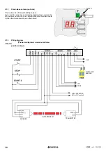
P.3 LD loop detector
P.3 allows to fit to LD terminal a vehicle detector (loop detector) that
works exactly as a safety device, like closing photocell.
In addition it can command a START pulse: when the vehicle
approaches the barrier, a START command is given and the barrier
opens.
Settings available:


