

9
S-PARK
- rev.1.1_06_2020
1 2 3 3 2 1
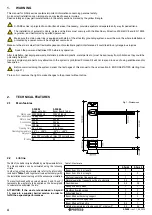
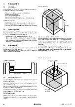
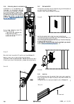
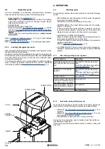
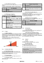
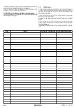
3.6.4
Limit switches
In order to adjust the stroke of the boom, open the cabinet door,
unlock the automation as explained above and use the two threaded
pins on the "V" reinforcement positioned above the gearbox.
Turn the two pins clockwise / counterclockwise to increase or
decrease the stroke of the boom and evaluate the most correct
position according to the inclination of the ground where the barrier
will be fitted.
Picture 17
LIMIT SWITCHES
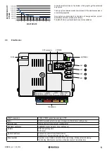
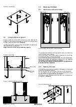
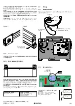
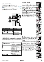
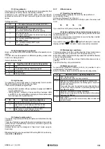
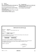
3.6.5
Mounting and adjusting of the spring
Before proceeding to balancing, make sure the spring is fitted to
the proper hole, considering the boom weight and length and
possible accessories, as outlined in Table 2.
There are three different springs (A/B/C) that can be matched to
three different holes (1/2/3).
Example:
if matching all the data you
get as result A3, it means spring A (MM010) fitted to hole 3.
Looking at the equalizer lever you will find 3 holes on the right side
and 3 holes on the left side. If the boom closes to the right side, use
the holes on the left side of the equalizer lever and viceversa.
Picture 18
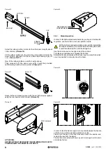
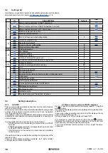
• Make sure the barrier is unlocked and put the boom to vertical
position.
• Lock it again.
• Drive the M12 hexagonal screw through the spring hole, and
put a washer as spacer. The screw’s head must be oriented as
shows
Picture 18
.
• Fit the spring to the equalizer lever, using the proper hole.
Put a washer in order to facilitate rotation.
• Tighten bolt and washer M12.
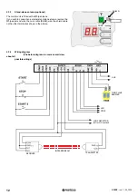
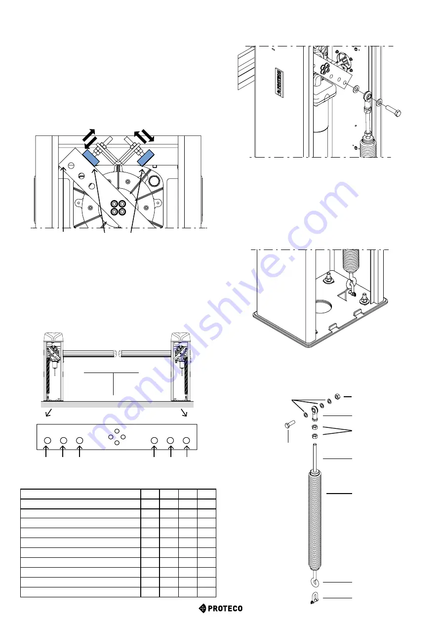
• Use the hook to secure the spring to barrier’s plate, as shows
Picture 19
.
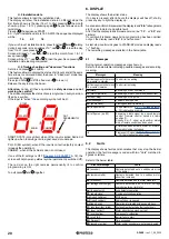
A
TTENTION: The barrier’s plate is provided with two fixing points,
on the left and right side. Make sure spring is hooked to the
proper fixing point according to the barrier’s hand.
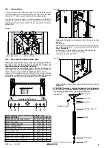
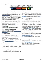
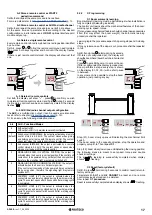
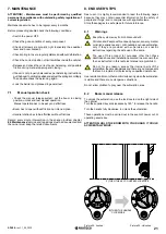
WASHER M12
JOINT M12
THREADED BAR M12
SCREW TE 12X45
SPRING
TRIGGER M8
Picture 20: Spring components
Legenda of springs
MMO10 A
MMO11 B
MMO12 C
BOOM FEATURES
2-3m 3-4m 4-5m 5-6m
BOOM (integrated with rubber profile)
A 2
A 1
B 2
B 1
BOOM + LED STRIP
A 2
A 1
B 2
B 1
BOOM + MOVING SUPPORT
A 1
B 3
B 1
C 1
BOOM + HANGING RACK
A 2
B 2
B 1
C 1
BOOM+HANGING RACK+MOVING SUPPORT A 1
B 2
B 1
-
ARTICULATED BOOM
B 2
B 1
C 3
C 2
BOOM + LED STRIP + MOVING SUPPORT
A 1
B 3
B 1
C 1
BOOM + LED STRIP + HANGING RACK
A 2
B 2
B 1
C 1
BOOM + LED STRIP + HANGING RACK
A 1
B 2
B 1
-
ARTICULATED BOOM + LED STRIP
A 1
B 1
C 2
C 1
Table 2: Guideline to matching of spring and equalizer lever hole
Picture 19
LH holes
RH holes
RH Barrier
LH Barrier
BOLT M12
HOOK
EQUALIZER LEVER LAYOUT
BOLT M12
EQUALIZER LEVER


