AS-5030 | ENGLISH
14
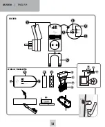
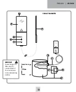
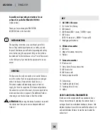
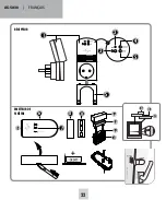
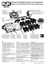
KEY
1 AS 5030.3 Receiver
2 Test button Test/Coding
3 LED Network
4 LED Window (RED = closed / GREEN = open)
5 LED Furnace
(RED = Furnace hot / GREEN = Furnace cold)
S Replugging safety device
6 Window transmitter
7 LED Status
8 Magnet for window transmitter
U Washers
9 Furnace transmitter
10 Thermo-sensor
11 Status button Furnace transmitter
12 LED Furnace hot
13 LED Furnace cold
14 Battery compartment lid
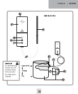
15. Exhaust pipe
16. Feedthrough hole (4 mm)
17. Fastening holes (2 mm)
H Holder
USE OF ADDITIONAL TRANSMITTERS
The device can be expanded with one window and one
furnace transmitter each, whereby the extractor hood is
no longer bound to an individual window or furnace. Each
individual window transmitter can enable the exhaust unit
and each individual furnace transmitter can disable the
exhaust unit.
Assembly and operating instructions for an
exhaust air controller Model AS-5030.3
(radio version)
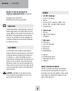
Thank you for purchasing the PROTECTOR
AS-5030.3 Exhaust Air Controller.
INTRODUCTION
The operating instructions are a constituent part of this
device. They contain important notes on safety, use and
disposal. Familiarise yourself with all operating and safety
notes before using the equipment. Only use the article as
described and for the listed areas of use. Pass all documents
to the third party if you transfer the equipment to a new
owner.
GENERAL
This device can be used as an exhaust air control device, as
an aid to monitor fresh air supply when commissioning an
exhaust air device (fume extractor hood, fan etc…).
This cannot replace self-monitoring to ensure fresh air
supply, but it can be supportive. This device only activates
the exhaust air system in the event of pressure equalisation
when a window or door is opened. The additional fresh air
streaming in can thus be drawn in from the outside.
ATTENTION
: When using this device for exhaust air control,
the shutter must be open to ensure adequate inflow of
fresh air!


