background image

AS-5030      |  ENGLISH

20

•   Empty batteries or faulty accumulator
•   Erroneous coding/channel selection
•   Fault through other radio installation 
  (i.e. mobile operation)
•   Unauthorised modifications / actions
•   Mechanical damage
•   Moisture damage
•   No proof of guarantee (purchase receipt)

Claims under warranty will be invalidated in the event of 
damage caused by non-compliance with the operating 
instructions. We do not accept any responsibility for conse-
quential damage! No liability will be accepted for material 
damage or personal injury caused by inappropriate operation 
or failure to observe the safety instructions. In such cases, 
the guarantee will be rendered void.

Liability limitation

The manufacturer is not liable for loss or damage of any kind 
including incidental or consequential damage which is the 
direct or indirect result of a fault to this product.

SAFETY NOTES

The warranty will be null and void in case of damages arising 
from violations of these operating instructions. We are not 
liable for consequential damages!

We accept no liability for material damages or injuries arising 
from inappropriate use or violation of the safety instructions. 
In such cases all warranty claims are null and void!

Do not use this product in hospitals or other medical 
facilities. Although this device transmits only relatively weak 
radio signals, the signals may in such locations result in 

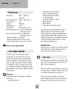
TECHNICAL DATA

Mains voltage: 

230 V ~, 50/60 Hz, 


approx. 1 W

Mains switching capacity:  1800 W / 8A, at cos phi = 1
Radio range up to: 

50 m

Frequency:   

433.92 Mhz

Transmitting power:  

< 5mW

Protection class: 

IP 20, only for dry rooms

Battery (window transmitter): 1 x 3V lithium type CR 2477  


   (lifetime approx. 2 years)

Battery (furnace transmitter): 3 x 1.5V alkaline AAA 


   (lifetime approx. 2 years)

•Maximum temperature at sensor 400°C
•Maximum heating capacity of the furnace 4,5 KW 
•Silicone cable of the sensor heat resistant up to 150°C

Never carry out repairs yourself!

2 YEAR LIMITED GUARANTEE

For two years after the date of purchase, the defect-
free condition of the product model and its materials is 
guaranteed. This guarantee is only valid when the device 
is used as intended and is subject to regular maintenance 
checks. The scope of this guarantee is limited to the repair 
or reinstallation of any part of the device, and is only valid 
if no unauthorised modifications or attempted repairs have 
been undertaken. Customer statutory rights are not affected 
by this guarantee.

Please note!

No claim can be made under guarantee in the following 
circumstances:
•   Operational malfunction

Summary of Contents for AS-5030.3

Page 1: ...AS 5030 3 BETRIEBSANLEITUNG OPERATING INSTRUCTIONS MODE D EMPLOI GEBRUIKSAANWIJZING ...

Page 2: ...AS 5030 DEUTSCH 2 S 5 4 3 2 1 EMPFÄNGER 6 8 FENSTER SENDER U 8c 8b 8a CODE CODE 7 6a Magnet Unterlegscheiben Fensterflügel Fensterrahmen Sender U 6 8 ...

Page 3: ...0 15 17 H 16 SENDER FÜR OFENROHR 12 10 14 11 13 9 Ofen Sensor Ofen 50cm WICHTIG Um eine Beschädigung des Ofen Sensors 10 zu vermeiden muss bei der Montage ein Mindestab stand von 50 cm zum Ofen zwingend eingehalten werden ...

Page 4: ...erung AS 5030 3 EINLEITUNG Die Bedienungsanleitung ist Bestandteil dieses Gerätes Sie enthält wichtige Hinweise für Sicherheit Gebrauch und Ent sorgung Machen Sie sich vor der Benutzung des Gerätes mit allen Bedien und Sicherheitshinweisen vertraut Benutzen Sie das nur wie beschrieben und für die angegebenen Ein satzbereiche Händigen Sie alle Unterlagen bei Weitergabe des Gerätes an Dritte aus ALL...

Page 5: ...tivieren Sie den OFEN SENDER 9 indem Sie die Status Taste 11 einmal betätigen Die im Sender einge bauten LED s leuchten auf Am EMPFÄNGER leuchtet die LED Ofen 5 auf und der Anlernvorgang wird abgeschlossen Durch Drücken der Status Taste 11 am Ofen Sender 9 können Sie den aktuellen Ofen Staus heiß oder kalt einstellen Dieser wird allerdings auch beim nächsten Status Wechsel automatisch übertragen 9...

Page 6: ...ters ermitteln Diese richtet sich nach a Der Leistung des Abluftgerätes in m h b Der Größe des zu öffnenden Fensters in m c Der Größe des Öffnungsspalts am Fenster in cm siehe Tabelle 1 Alle SENDER löschen 1 Drücken Sie am Empfänger den Taster 2 für 2 Sekun den Die LED NETZ 3 fängt an zu blinken 2 Drücken Sie erneut den Taster 2 für 2 Sekunden Am EMPFÄNGER endet das blinken der LED NETZ 3 und der ...

Page 7: ...ln Sie die Abluftluftleistung Ihres Abluftgerätes in m h Sie finden die Abluftluftleistung auf dem Typen schild oder in der Betriebsanleitung Ihres Abluftgerätes z B Dunstabzugshaube 2 Messen Sie die innere Breite und Höhe des Fensters und errechnen Sie die Fenstergröße in m2 Breite x Höhe m z B 0 8 m x 1 0 m 0 8m Fenstergröße 3 Bestimmen Sie anhand der Tabelle aus der Abluftluft leistung und der ...

Page 8: ...gerät muss an bleiben 3 Fenster schließen Abluftgerät muss an bleiben MONTAGE DES OFEN SENDERS Montageanleitung Ofen Sender 9 einschließlich Thermo Sensor 10 Hinweis Um Verbrennungen an Ihrer Haut zu vermeiden sollte der Ofen aus und abgekühlt sein Der Thermo Sensor 10 wird durch ein Loch in das Abgasrohr Ihres Ofens geführt und mittels beigelegtem Haltebügel mit dem Ofenrohr verschraubt Der Sende...

Page 9: ...aline Typ AAA Lebensdauer ca 2 Jahre maximale Temperatur Sensor 400 C maximale Heizleistung Ofen 4 5 KW Silikonleitung des Fühlers bis 150 C hitzebeständig Thermo Sensor 10 vom Ofen Sender ist 38 C 1 Abluftgerät EINschalten und das Fenster ist geschlossen Abluftgerät darf nicht anlaufen 2 Fenster öffnen Abluftgerät muss anlaufen 3 Fenster schließen Abluftgerät muss ausschalten BEDEUTUNG DER LED AN...

Page 10: ...ial nicht achtlos liegen Plastikfolien tüten Styroporteile etc könnten für Kinder zu einem gefährlichen Spielzeug werden Keine eigenen Reparaturversuche durchführen 2 JAHRE BESCHRÄNKTE GARANTIE Es wird für die Dauer von 2 Jahren ab Kaufdatum gewährlei stet dass dieses Produkt frei von Defekten in den Materialien und in der Ausführung ist Dies trifft nur zu wenn das Gerät in üblicher Weise benutzt ...

Page 11: ...Arbeitsweise die Sicherheit oder den Anschluss des Geräts haben Gehen Sie vorsichtig mit dem Produkt um durch Stöße Schläge oder dem Fall aus bereits geringer Höhe wird es beschädigt DE Diese Bedienungsanleitung ist eine Publikation der Protector GmbH An den Kolonaten 37 26160 Bad Zwischenahn Diese Bedienungsanleitung entspricht dem technischen Stand bei Drucklegung Änderung in Technik und Ausstat...

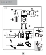
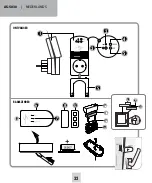
Page 12: ...AS 5030 ENGLISH 12 S 5 4 3 2 1 RECEIVER 6 8 WINDOW TRANSMITTER U 8c 8b 8a CODE CODE 7 U 6 8 6a ...

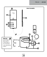
Page 13: ...13 10 15 17 H 16 FURNACE TRANSMITTER 12 10 14 11 13 9 Furnace Sensor Furnace 50cm IMPORTANT To prevent damage to the thermo sensor 10 a minimum distance of 50 cm from the furnace must be maintained during installation ...

Page 14: ...air controller Model AS 5030 3 radio version Thank you for purchasing the PROTECTOR AS 5030 3 Exhaust Air Controller INTRODUCTION The operating instructions are a constituent part of this device They contain important notes on safety use and disposal Familiarise yourself with all operating and safety notes before using the equipment Only use the article as described and for the listed areas of use...

Page 15: ... a socket Insert the device to be connected into the socket of the receiver and screw the replugging safety device S on As soon as the LED NETWORK 3 on the receiver lights up this is ready for operation Note The receiver should not be mounted behind a metal panel as the range can be restricted by this ATTENTION Always check whether the power consumption of the connected device is less than or equa...

Page 16: ...urnace and screwed to the exhaust pipe with the enclosed mounting bracket The transmitter and screw the housing tight with the enclosed washer Replace the board after this 3 Press the housing upper section of the window transmit ter onto the housing lower section 4 Mount the housing lower section with the magnet 8 at the intended location with the enclosed adhesive pad ATTENTION The distance betwe...
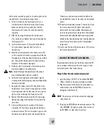
Page 17: ...shorter 1 Drill a 4 mm hole for the thermo sensor 10 at a suitable location in the exhaust pipe of your furnace Make sure that the hole is positioned so that the thermo sensor 10 cannot be seen after assembly if possible 2 Slide the mounting bracket over the thermo sensor 10 but do not yet tighten the screw for fastening the thermo sensor 10 3 Insert the thermo sensor 10 into the hole drilled for ...
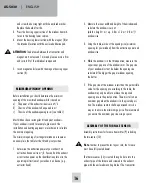
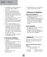
Page 18: ...3 begins to flash 5 Activate the window TRANSMITTER by holding the magnet once on the housing 6a and removing it again The LED integrated in the transmitter lights up At the RECEIVER the LED Window 4 lights up and the teach in process is completed 6 Press the RECEIVER button 2 again for 2 seconds the yellow LED NETWORK 3 begins to flash 7 Place the batteries 3x AAA in the furnace TRANSMITTER 9 The...

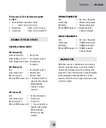
Page 19: ... long as the fault is present Thermo sensor 10 of the furnace transmitter is 38 C 1 Switch ON exhaust and window is closed Exhaust unit must not start up 2 Open window Exhaust unit must start up 3 Close window Exhaust unit must switch off MEANING OF THE LED DISPLAYS RECEIVER CONTROL CENTRE LED Network 3 Yellow continuously lit Basic position Yellow flashing at the start No transmitter taught in Ye...

Page 20: ...rranty claims are null and void Do not use this product in hospitals or other medical facilities Although this device transmits only relatively weak radio signals the signals may in such locations result in TECHNICAL DATA Mains voltage 230 V 50 60 Hz approx 1 W Mains switching capacity 1800 W 8A at cos phi 1 Radio range up to 50 m Frequency 433 92 Mhz Transmitting power 5mW Protection class IP 20 ...

Page 21: ...l toys for children The device is suitable only for dry interior rooms not bathrooms and other moist places Do not allow the device to get moist or wet There is a danger of lethal electric shock In industrial institutions the accident prevention regulations of the Association of Commercial Professional Associations for electrical installations and equipment must be observed Please consult a specia...

Page 22: ...AS 5030 FRANÇAIS 22 S 5 4 3 2 1 RÉCEPTEUR 6 8 EMETTEUR DE FENÊTRE U 8c 8b 8a CODE CODE 7 U 6 8 6a ...

Page 23: ... 23 10 15 17 H 16 EMETTEUR DE POÊLE 12 10 14 11 13 9 Capteur du four Four 50cm IMPORTANT Pour éviter d endommager le capteur du four 10 une distance minimale de 50 cm du four doit être respectée pendant l installation ...

Page 24: ...30 3 PROTECTOR Le manuel d utilisation fait partie intégrante de l appareil Il contient des consignes importantes concernant la sécurité l utilisation et la mise au rebut de l appareil Familiarisez vous avec toutes les consignes d utilisation et de sécurité avant de manipuler l appareil Utilisez le uniquement comme expliqué et pour les domaines d application spécifiés Si vous confiez l appareil à ...

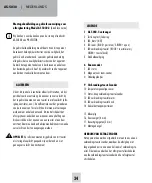
Page 25: ... les points de collage Montez la partie inférieure du boîtier de l émetteur de fenêtre 6 au point prévu à l aide du ruban adhésif double face fourni Alternativement l élément inférieur du boîtier est doté d un trou préper cé qui permet de visser l émetteur de fenêtre sur le MONTAGE DU RECEPTEUR Branchez le récepteur de l AS 5030 3 à une prise électrique Branchez l appareil à piloter dans le port d...

Page 26: ... d ouverture minimale Nous recommandons de fixer la cote d ouverture minimale à l aide d une entretoise châssis A cet effet retirez avec précaution la platine de la partie inférieure du boîtier et vissez le boîtier à l aide de la vis fournie Remettez ensuite la platine en place 3 Appuyez l élément supérieur du boîtier de l émetteur de fenêtre sur l élément inférieur du boîtier 4 Montez la partie i...

Page 27: ... émetteur de poêle 9 ne sont pas codés à la livraison et doivent faire l objet d un apprentissage par rapport au récepteur lors de la première mise en service MONTAGE DE L EMETTEUR DE POELE Notice de montage de l émetteur de poêle 9 avec son capteur thermique 10 Remarque Pour éviter de vous brûler le poêle doit être éteint et froid Le capteur thermique 10 est passé par un trou dans le conduit d éc...

Page 28: ...clignoter Veuillez respecter scrupuleusement l ordre indiqué 1 Branchez le connecteur de l appareil à commuter par ex la hotte aux RECEPTEUR et montez le détrompeur S REMARQUE Sans le détrompeur S le système ne fonctionne pas 2 Branchez ensuite le RECEPTEUR à une prise secteur La DEL Réseau 3 s allume en jaune après l autotest du RECEPTEUR pour indiquer son bon fonctionnement 3 Appuyez pendant 2 s...

Page 29: ...enêtre se ferme ROUGE et VERTE clignotante à un rythme de 0 5 sec pile d émetteur de fenêtre épuisée 2 Appuyez une nouvelle fois pendant 2 secondes sur la touche 2 Sur l EMETTEUR la DEL Réseau 3 ne clignote plus et le processus de suppression est terminé pour tous les EMETTEURS CONTROLE FONCTIONNEL La température du capteur thermique 10 de l émetteur de poêle 9 est décisive pour le contrôle foncti...

Page 30: ...ndirect Nous déclinons également toute responsabilité en cas de dommages survenus sur l appareil ou des personnes suite à une manipulation non conforme ou la non observation des consignes de sécurité La garantie s annule automatiquement dans ces cas là EMETTEUR DE POELE Eteinte état de repos mode veille Verte clignotante le POELE se refroidit ROUGE clignotante le POELE se chauffe ROUGE et VERTE cl...

Page 31: ...uelconques y compris les dommages consécutifs ou accessoires qui résultent directement ou indirectement de la défaillance de ce produit CONSIGNES DE SÉCURITÉ Tout dommage résultant d un non respect des présentes instructions a pour effet d annuler la garantie Nous décli nons toute responsabilité pour les dommages consécutifs De même le constructeur n assume aucune responsabilité en cas de dommage ...

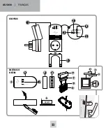
Page 32: ...AS 5030 NEDERLANDS 32 S 5 4 3 2 1 6 8 U 8c 8b 8a 6a CODE CODE 7 ONTVANGER RAAM ZENDER U 6 8 ...

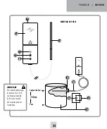
Page 33: ...15 17 H 16 12 10 14 11 13 9 VERBRANDINGSTOESTEL ZENDER Ovensensor Oven 50cm BELANGRIJK Om beschadiging van de ovensensor 10 te voorkomen moet tijdens de installatie een minimale afstand van 50 cm tot de oven worden aangehouden ...

Page 34: ...Wij danken u voor de aankoop van de sturing afvoerlucht AS 5030 3 van PROTECTOR De gebruikershandleiding maakt deel uit van dit apparaat Deze bevat belangrijke instructies voor de veiligheid het gebruik en het onderhoud Lees vóór gebruik aandachtig alle gebruikers en veiligheidsinstructies van het apparaat Gebruik het apparaat enkel zoals beschreven en enkel voor het bestemde gebruik Geef bij over...

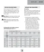
Page 35: ...et onderste deel van de behuizing van de raam zender 6 op de uitgekozen plaats met behulp van de meegeleverde dubbelzijdige plakstrip In het onderste deel van de behuizing zit een gat zodat de raam zender eventueel ook op het raamkozijn kan INSTALLATIE VAN DE ONTVANGER Steek de ontvanger van de AS 5030 3 in een stopcontact Steek het te schakelen apparaat in het stopcontact van de ontvanger en schr...

Page 36: ...0 Opmerking Om verbranding van de huid te voorkomen moet het verbrandingstoestel uitgeschakeld en afgekoeld zijn worden vastgeschroefd Verwijder daartoe de printplaat voorzichtig uit het onderste deel van de behuizing en schroef de behuizing vast met de meegeleverde schroef Plaats daarna de printplaat weer terug 3 Druk het bovenste deel van de behuizing van de raam zender vast op het onderste deel...

Page 37: ...voelige sensor 10 wordt door een gat in de afvoerpijp van uw verbrandingstoestel gestoken en met behulp van de meegeleverde montagebeugel op de afvoerpijp vastgeschroefd De zender mag niet door een metalen plaat paneel afgeschermd worden omdat hierdoor het radiosignaal gehinderd en de reikwijdte beperkt zouden kunnen worden 1 Boor op een geschikte plaats een gat van 4 mm in de afvoerpijp van uw ve...

Page 38: ...e LED NETZ NET 3 met knipperen Het afmeldingsproces voor alle ZENDERS wordt afgesloten OPMERKING Zonder de stekkerbeveiliging S werkt het apparaat niet 3 Steek de ONTVANGER daarna in een stopcontact De LED NETZ NET 3 gaat bij een juiste werking van de ONTVANGER na zelftest geel branden 4 Houd op de ONTVANGER de drukknop 2 twee seconden ingedrukt tot de gele LED NETZ NET 3 begint te knipperen 5 Act...

Page 39: ...TEL zender batterij leeg FUNCTIONELE WERKING TESTEN Bepalend voor de functionele werking van de afzuigsysteem besturing is de temperatuur van de temperatuurgevoelige sensor 10 van de verbrandingstoestel zender 9 Temperatuurgevoelige sensor 10 van de verbrandingstoestel zender is 38 C 1 Afzuigtoestel INschakelen het raam is gesloten afzuigtoestel moet starten 2 Raam openen afzuigtoestel moet blijve...

Page 40: ...r het verlies of de beschadiging van om het even welke soort met inbegrip van bijkomende of vervolgschade die direct of indirect het resultaat zijn van een fout in het product STORINGEN In enkele gevallen kunnen er door interferentie met andere soortgelijke draadloze apparaten storingen optreden Dit kan normaal gesproken worden verholpen door de positione ring van de componenten te controleren en ...

Page 41: ...vervalt elke aanspraak op garantie Gebruik dit product niet in ziekenhuizen of soortgelijke me dische instellingen Hoewel dit toestel slechts relatief zwakke radiosignalen uitzendt zouden die daar tot werkingsstoornis sen van levensbelangrijke systemen kunnen leiden Hetzelfde geldt mogelijk in andere omgevingen Om veiligheids en vergunningsredenen CE is het niet toegestaan om op eigen houtje het p...

Page 42: ......

Page 43: ......

Page 44: ...ät den folgenden Richtlinien entspricht RoHS 2011 65 EU LVD 2014 35 EU EMC 2014 30 EU RED 2014 53 EU Die KONFORMITÄTSERKLÄRUNG kann unter folgender Adresse abgerufen werden http www protector24 de download ce as50303ce pdf 24 07 2019 WWW PROTECTOR24 DE ...

Reviews: