background image

ENGLISH  |    

AS-510

15

2 YEAR LIMITED GUARANTEE

For two years after the date of purchase, the defect-
free condition of the product model and its materials is 
guaranteed. This guarantee is only valid when the device 
is used as intended and is subject to regular maintenance 
checks. The scope of this guarantee is limited to the repair 
or reinstallation of any part of the device, and is only valid 
if no unauthorised modifications or attempted repairs have 
been undertaken. Customer statutory rights are not affected 
by this guarantee.

Please note!

No claim can be made under guarantee in the following 
circumstances:
•   Operational malfunction
•   Empty batteries or faulty accumulator
•   Erroneous coding/channel selection
•   Fault through other radio installation 
  (i.e. mobile operation)
•   Unauthorised modifications / actions
•   Mechanical damage
•   Moisture damage
•   No proof of guarantee (purchase receipt)

Claims under warranty will be invalidated in the event of 
damage caused by non-compliance with the operating 
instructions. We do not accept any responsibility for conse-
quential damage! No liability will be accepted for material 
damage or personal injury caused by inappropriate operation 
or failure to observe the safety instructions. In such cases, 
the guarantee will be rendered void.

illuminate. The power LED (6) on the RECEIVER stops 
flashing and the programming process is complete.  

5.   The TRANSMITTER has now been programmed to the 

RECEIVER and the AS-510 is ready for use.

6.   The receiver goes into learn mode for 20 seconds after 

every mains power failure. If no new window transmitter 
is taught then the old encoding remains. 

FUNCTION TEST

1.   Switch the exhaust device ON and open the window 
  > Exhaust device must start. 
2.   Close window  
  > Exhaust device must switch off.

MALFUNCTIONS

In isolated cases, faults may occur due to interference by 
other, similar radio units. It normally suffices if you check 
(and if necessary change) the location of the components.

TECHNICAL DATA

Mains voltage: 

230 V ~, 50/60 Hz, 


approx. 1 W

Mains switching capacity:  1800 W / 8A, at cos phi = 1
Radio range up to: 

50 m

Frequency:   

433.92 Mhz

Protection class: 

IP 20 * only for dry rooms

Battery (transmitter): 

CR2032


(lifetime approx. 1 year)

Never carry out repairs yourself!

Summary of Contents for AS-510

Page 1: ...AS 510 BETRIEBSANLEITUNG OPERATING INSTRUCTIONS ...

Page 2: ...AS 510 DEUTSCH 2 FENSTER SENDER FENSTER GESCHLOSSEN FENSTERRAHMEN FENSTERFLÜGEL FENSTER GEÖFFNET 11 3a 3b 3c 10 2 2 8 Abstand Magnet zum Sender max 7 mm Abstand Magnet zum Sender min 10 mm ...

Page 3: ...DEUTSCH AS 510 3 1 5 ZENTRALE EMPFÄNGER 6 4 5 ...

Page 4: ...Modell AS 510 Funkversion Wir danken Ihnen für den Kauf der PROTECTOR Funk Abluftsteuerung AS 510 EINLEITUNG Die Bedienungsanleitung ist Bestandteil dieses Gerätes Sie enthält wichtige Hinweise für Sicherheit Gebrauch und Ent sorgung Machen Sie sich vor der Benutzung des Gerätes mit allen Bedien und Sicherheitshinweisen vertraut Benutzen Sie das nur wie beschrieben und für die angegebenen Ein satz...

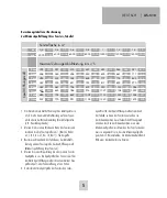
Page 5: ... das erforderliche Öffnungsmaß erreichen Auch in der Schwenkposition muss eine Mindestspaltgröße erreicht werden Der Fenster Sender muss so angebracht sein dass die Mindestspaltgröße gesichert ist Wir empfehlen die Mindestspaltgröße mit Hilfe eines Abstandhalters zu fixieren Berechnungstabelle zur Bestimmung der Mindestspaltöffnung Ihres Fensters Tabelle1 0 2 2000 199 246 294 342 389 437 485 532 0...

Page 6: ...ube in den EMPFÄNGER 3 Danach stecken Sie den EMPFÄNGER in eine Netzsteck dose Die LED NETZ 6 blinkt bei ordnungsgemäßer Funktion des EMPFÄNGERS gelb Der Empfänger ist im MONTAGE DES EMPFÄNGERS Stecken Sie den Empfänger der AS 510 in eine Steckdose Stecken Sie das zu schaltende Gerät in die Steckdose des Empfängers Sobald LED NETZ 5 am Empfänger leuchtet ist dieser betriebsbereit Hinweis Der Empfä...

Page 7: ...ung irgendwelcher Art einschließlich der beiläufigen oder Folge schäden haftbar die direkt oder indirekt aus der Störung dieses Produktes resultieren Lernmodus solange die LED blinkt 20 Sekunden 4 Aktivieren Sie den Fenster SENDER innerhalb dieser 20 Sekunden indem Sie den Magnet 3 einmal an den Sender 2 halten und wieder entfernen Am EMPFÄNGER endet das Blinken der LED NETZ 6 die im Sender eingeb...

Page 8: ...dieser Bedienungsan leitung verursacht werden erlischt der Garantieanspruch Für Folgeschäden übernehmen wir keine Haftung Bei Sach oder Personenschäden die durch unsachgemäße Handha bung oder Nichtbeachten der Sicherheitshinweise verursacht werden übernehmen wir keine Haftung In solchen Fällen erlischt jeder Garantieanspruch Der Aufbau der Zentrale Empfänger entspricht der Schutzklasse 1 Als Spann...

Page 9: ...DEUTSCH AS 510 9 ...

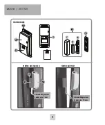
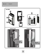
Page 10: ...AS 510 ENGLISH 10 TRANSMITTER WINDOW CLOSED WINDOWFRAME WINDOW LEAF WINDOW OPEN 2 Distance Magnet to Transmitter max 7 mm Distance Magnet to Transmitter min 10 mm 11 3a 3b 3c 10 2 8 ...

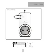
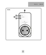
Page 11: ...ENGLISH AS 510 11 1 5 RECEIVER 6 4 5 ...

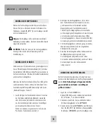
Page 12: ...uctions for exhaust control model AS 510 wireless version Thank you for purchasing the PROTECTOR wireless exhaust control AS 510 INTRODUCTION The operating instructions are a constituent part of this device They contain important notes on safety use and disposal Familiarise yourself with all operating and safety notes before using the equipment Only use the article as described and for the listed ...

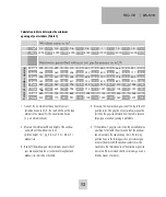
Page 13: ...e the internal width and height of the window and work out the window size in m width x height m e g 0 8 m x 1 0 m 0 8 m window size 3 Read off the window gap size minimum gap at side of your window where the air extraction throughput and window size intersect on the table 0 2 2000 199 246 294 342 389 437 485 532 0 3 3000 252 311 369 427 486 544 603 661 0 4 4000 297 365 432 500 567 635 702 770 0 5...

Page 14: ... the switch 11 into position I to turn the device on 4 Activate the window TRANSMITTER by holding the magnet 3 against the transmitter 2 once and then removing it The LED installed in the transmitter will RECEIVER ASSEMBLY Insert the receiver for the AS 510 into a socket Plug the equipment that you wish to switch into the receiver socket The receiver is ready for operation as soon as the power LED...

Page 15: ...e do not accept any responsibility for conse quential damage No liability will be accepted for material damage or personal injury caused by inappropriate operation or failure to observe the safety instructions In such cases the guarantee will be rendered void illuminate The power LED 6 on the RECEIVER stops flashing and the programming process is complete 5 The TRANSMITTER has now been programmed ...

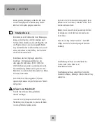
Page 16: ...rer is not liable for loss or damage of any kind including incidental or consequential damage which is the direct or indirect result of a fault to this product Safety notes The warranty will be null and void in case of damages arising from violations of these operating instructions We are not liable for consequential damages We accept no liability for material damages or injuries arising from inap...

Page 17: ...ENGLISH AS 510 17 ...

Page 18: ......

Page 19: ......

Page 20: ...rät in Übereinstimmung mit den grundlegenden Anforderungen und den übrigen einschlägigen Bestimmungen befindet KONFORMITÄTSERKLÄRUNG kann unter folgender Adresse gefunden werden http www protector24 de download ce AS 510ce pdf 16 11 2018 WWW PROTECTOR24 DE ...

Reviews: