ENGLISH | WA-5
11
RECEIVER
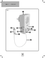
device is to be switched ON or OFF. Slide the switch
to the OFF setting (crossed out socket) in order to
switch a connected device off if the sensor elec-
trodes (9) come into contact with water. The water
detector switches the connected device on when the
selector is set to ON.
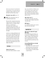
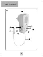
Alarm volume switch
(10)
Use this switch to set the volume of the alarm to
one of 3 levels. MAX is the highest setting and MIN
is the lowest setting.
RESET button
(3)
Press the RESET button briefly in order to cancel the
alarm after water has been detected.
MALFUNCTION
Alarm cannot be switched off using the
RESET button
If it is not possible to deactivate the alarm using
this button then it is still detecting water. This can
happen, for example, if water has penetrated the
sensor. In this event remove the water detector
from the socket and allow the sensor to dry. You
can also dismantle the sensor and then dry it with
a dry cloth.
No alarm although both sensor electrodes
are submerged in water
1. Sensor electrodes have no contact to the sensor
cable
>
check the pinch on the ring cable lug.
2. Sensor electrodes are contaminated
>
clean
the sensor electrodes, e.g. with fine sandpaper
or a glass fibre eraser.
location using a small screw. You should select the
mounting location in such a way that any water can
be detected as quickly as possible. The two sensor
electrodes (9) should be just above the floor.
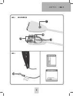
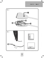
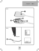
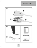
Adjusting the sensor cable
(figures 2 + 3)
NOTE
: disconnect the water detector from the
socket before shortening the cable.
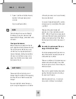
If the sensor cable is too long then you can shorten
the cable as necessary. To do this you will need the
supplied ring cable lug, a small Philips screwdriver
and pliers (e.g. combination pliers).
First remove the casing screw (7) using the
screwdriver and remove the lid from the sensor. The
two electrode screws are now exposed and you can
remove these also. Caution, the electrodes are then
also released.
Use the pliers to shorten the cable and ensure that
you do not cut too much off. Remove the outer insu-
lation at the point of cutting to a length of approx.
15 mm and the insulation on the wires to approx.
5 mm, measured from the cut point. Push a ring
cable lug onto one of the two exposed wires and
then pinch the back of the ring cable lug together
using the pliers. Alternatively the wires can also be
soldered to the cable lugs.
SETTINGS
Function selector switch
(11)
Use this selector switch to set whether a connected
Summary of Contents for WA-5
Page 1: ...WA 5 BETRIEBSANLEITUNG OPERATING INSTRUCTIONS MODE D EMPLOI GEBRUIKSAANWIJZING ...
Page 2: ...ABB 1 WA 5 DEUTSCH 2 3 5 7 2 6 4 9 8 11 10 1 ...
Page 3: ...ABB 2 ABB 3 DEUTSCH WA 5 3 13 12 7 14 14 WASSER SENSOR ...
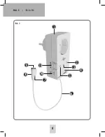
Page 8: ...WA 5 ENGLISH 8 FIG 1 3 5 7 2 6 4 9 8 11 10 1 ...
Page 9: ...ENGLISH WA 5 9 FIG 2 FIG 3 13 12 7 14 14 ...
Page 14: ...WA 5 FRANÇAIS 14 SECT 1 3 5 7 2 6 4 9 8 11 10 1 ...
Page 15: ...FRANÇAIS WA 5 15 SECT 2 SECT 3 13 12 7 14 14 ...
Page 20: ...WA 5 NEDERLANDS 20 AFB 1 3 5 7 2 6 4 9 8 11 10 1 ...
Page 21: ...NEDERLANDS WA 5 21 AFB 2 AFB 3 13 12 7 14 14 ...
Page 26: ......
Page 27: ......

