1. Safety Information
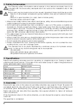
The following safety informations and all advices in this manual eventually have to be
extended with the local safety standards which are valid at the installation site of this
machine.
Before each use this machine have to be visually inspected! Check the following points:
- Density of all hydraulic components (pump, cylinder, tube and all hydraulic connec-
tors)
- Frame is in good condition (no crack, bent or broken parts)
- No loose screws and nuts in sight
• Always wear safety helmet, face shield, hand gloves, saftey shoes and additional personal
safety equipment to prevent workplace accidents.
• Some parts being pressed may have a tendency to pop out of the press or explode un-
derpressure. Protect yourself accordingly. Keep hands away from the pressure head and
out of support rod holes. This press is designed for pressing, bending, and straightening
purposes only. DO NOT compress springs or other objects that could be ejected from the
press. DO NOT compress objects that could shatter.
• The adjust beam has to be mounted horizontal and must be secured with both pins in all
four mounting holes.
• Always center the work piece on the table plates and center the pressure head on the work
piece to prevent injury by ejection of the work piece.
• Do not operate this press beyond it rated capacity.
• Please understand the max. working stroke before operate, Do not overload the max.
working stroke, so as not to damage parts.
This machine has to be yearly inspected by a technical surveyor for hydraulic compo-
nents. In this survey the following parts has to be inspected:
- All weld joints
- Pump and cylinder bases and sockets
- All hydraulic tubes and hydraulic connectors
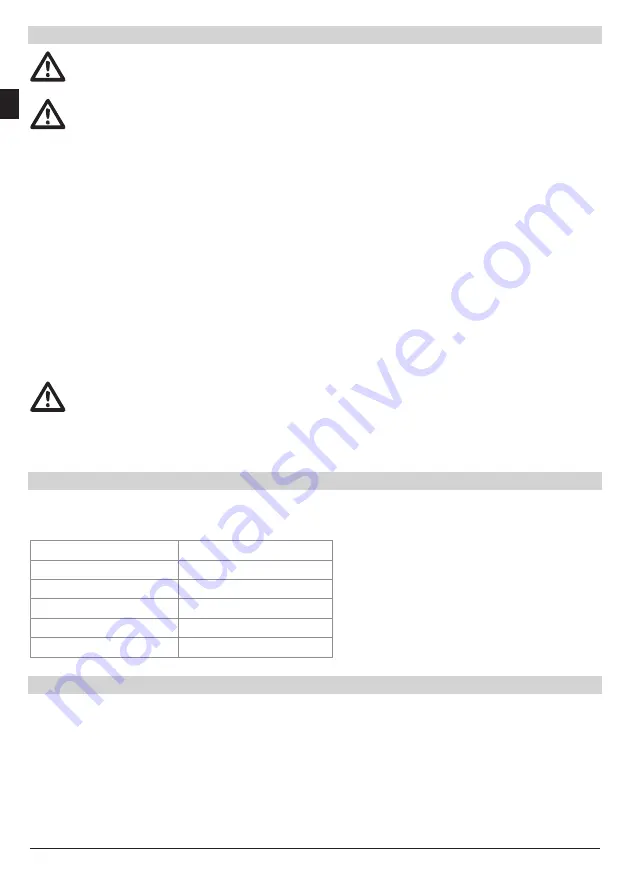
2. Specification
Manual self-standing workshop press for assembly or straightening work. Casing is made of
welded quality steel sections. The height of the work table is easy to adjust. Integrated mano-
meter, automatic piston return function.
Type
WZWP-020M
Max. Capacity
20t
Working height
0 - 910 mm
Working width
≤ 460 mm
Dimensions WxDxH
845 x 420 x 1.680 mm
Net weight
83 kg
3. Assembly
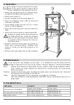
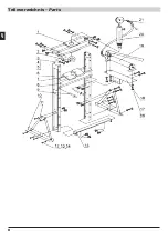
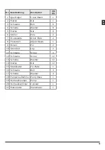
Mount both legs (10) on the poles (6) according schamtics (see page 8). Mount fix plate (15)
and adjust beam (8, only with pins). Mount cross beam (1) and fixed base (18). Finally mount
all hydraulic parts: handle pump (19), cylinder (20), manometer (21) and hydraulic tube.
Fasten alle bolts and nuts after final assembly. Give special attention to fasten all hydraulic
screw-connections.
If the manometer shows in the wrong direction, you can change the angle by using the upper
check nut.
The assembly is completed.
6
EN


