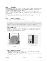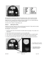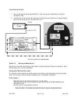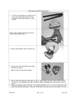
Electrical inputs and outputs are provided at a single eight-pin socket. An 8-pin connector providing
screw fastening of up to #16 gauge conductors is provided with the 500 Series metering flow switch.
Replacement 8-pin connectors can be obtained from Proteus, P/N 440157 or from electrical distributors,
On-Shore Technology P/N EDZ1550/8, or Digi-Key P/N ED1966-ND.
See Section 10 for installation of Digital Display units.
Section 7
Selecting Trip Points
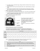
Adjustment of trip points in steps of 6% of the rated flow range is made with a 16-step switch and a single
turn potentiometer accessed through the cover of the electronics.
Tool Required
: A fine flat screwdriver
1. Identify the Part Number of the 500 Series metering flow switch being adjusted. This is noted on the
product label.
2. Select the Trip Point Flow chart that applies to your metering flow switch.
3. Look across the row to identify the flow rate that is immediately higher than your required trip point.
4. Look up the column with the selected trip point flow rate to identify the required switch position.
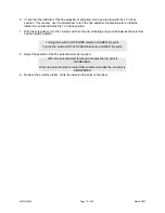
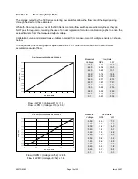
5. Peel away the protective label covering the 16-step switch and the fine adjustment potentiometer.
The orientation of the 16-position
switch is indicated by small arrow.
The orientation of the fine
adjustment potentiometer is
indicated by two indents.
Trip point adjustment controls.
500TRM-002
Page 12 of 22
March 2007


