500TRM-002
Page 18 of 22
March 2007
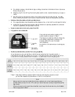
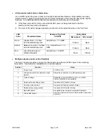
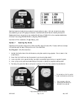
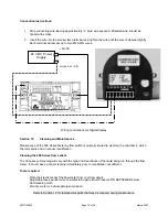
onnection instructions:
1. Strip connecting wire leaving approximately ¼” bare wire exposed. Stranded wire should be
s clamped tightly.
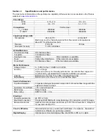
Wiring connections for Digital Display
ection 10
Cleaning and Maintenance
C
tinned with solder.
2. Insert the wire into the screw-clamp terminal and tighten the wire until the wire i
Each terminal will accept up to two #14 AWG wires.
S
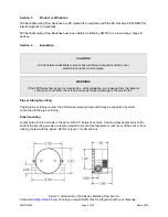
Maintenance of the 500 Series Metering flow switch is normally limited to cleaning the chamber in which
leaning the 500 Series flow sensor
he frequency of cleaning will vary with the type and cleanliness of
ng run through the flow
ols required:
Wrenches to disconnect the flow meter fr
cts P/N EEPS5400 Medium
tergent solution.
the rotor spins and an annual recalibration.
C
T
the liquid bei
meter. In most cases, annual cleaning immediately prior to recalibration is sufficient.
To
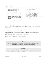
Adjustable face spanner wrench similar to Eugene Ernst Produ
Soft
cleaning
cloth
om your flow circuit.
Alcohol, water or a dilute de
+24VDC
24 V-DC Power
Refer to Section 12 for replacement parts that may be required during maintenance.
Supply
Ground or
-ve

