background image

PD6870 Explosion-Proof Loop-Powered Process Meter 

Instruction Manual 


7


Installation 

For Installation in USA:

 The PD6870 must be in-

stalled in accordance with the National Electrical 

Code (NEC) NFPA 70. 

For Installation in Canada:

 The PD6870 must be in-

stalled in accordance with the Canadian Electrical 

Code CSA 22.1. All input circuits must be derived 

from a CSA approved Class 2 source.


For European Community:

 The PD6870 must be in-

stalled in accordance with the ATEX directive 

2014/34/EU and the product certificate Sira 

10ATEX1116X.


  Installation and service should be performed only 

by trained service personnel. Service requiring 

replacement of internal components must be 

performed at the factory. 

  Disconnect from supply before opening 

enclosure. Keep cover tight while circuits are 

alive. Conduit seals must be installed within  

18" (450mm) of the enclosure. 


All controls and wiring connections are located on the 

display module that is accessed by removing the en-

closure cover. The controls can be accessed without 

removing the display module. The wiring connections 

can be accessed by removing the display module 

which is secured to the enclosure by two captive 

screws.  

Unpacking 

Remove the meter from box. Inspect the packaging 

and contents for damage. Report damages, if any, to 

the carrier. 
If any part is missing or the meter malfunctions, 

please contact your supplier or the factory for 

assistance. 

Pre-Installed Conduit Plug 

The PD6870 is supplied with one pre-installed conduit 

plug for installations that do not require the use of 

both conduit entries. The conduit/stopping plug in-

cludes an internal hexagonal socket recess for  

removal. The conduit plug and its factory installation 

are included in all hazardous area approvals of this 

product. 


  In hazardous areas, conduit and conduit/stopping 

plugs require the application of non-setting 

(solvent free) thread sealant. It is critical that all 

relevant hazardous area guidelines be followed for 

the installation or replacement of conduit or plugs. 


Mounting 

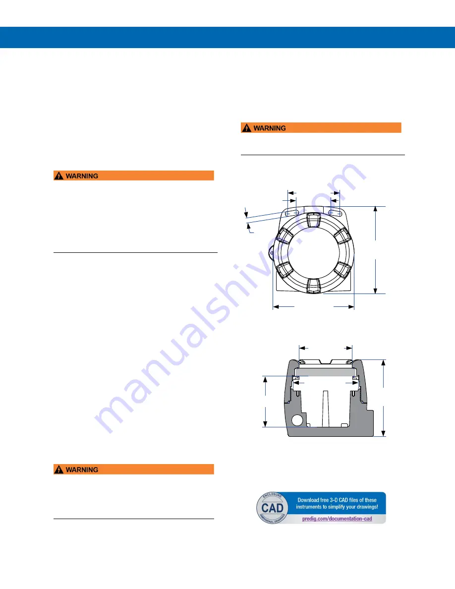
The PD6870 has two slotted mounting flanges that 

may be used for pipe mounting or wall mounting. 

Alternatively, the unit may be supported by the  

conduit using the conduit holes provided. 
Refer t

Figure 1

 and 

Figure 2

. 


  Do not attempt to loosen or remove flange bolts 

while the meter is in service. 

Dimensions 

All units: inches (mm) 


Figure 1. Enclosure Dimensions – Front View 


Figure 2. Enclosure Dimensions – 

Side Cross Section View 

Note:

 The supplied conduit plug may extend up to 0.6 

in [15 mm] from the conduit opening when installed. 


3.35 (85.1)

2.25 (57.1)

5.25 (133.4)

(143.5)

5.65

(8.2)

0.32

3.35 (85.0)

4.15 (105.5)

3.22 (81.9)

(123.5)

4.86

Summary of Contents for PD6870

Page 1: ...nt Loop Powered Backlight Option Operating Temperature Range 40 to 75 C 40 to 167 F Zero Span Potentiometer Adjustments for Easy Field Scaling Conformal Coated PCBs for Dust and Humidity Protection FM...

Page 2: ...t of the defective unit See Warranty Information and Terms Conditions on www predig com for complete details 2021 Precision Digital Corporation All rights reserved Introduction The ProtEX FarVu PD6870...

Page 3: ...ag that can be customized with three lines of text Each tag comes with a stainless steel wire and lead seal for easy mounting wherever you need Dimensions Useful Tools PD9501 Multi Function Calibrator...

Page 4: ...er Jam Screw 8 Connections 8 Wiring Diagrams 8 Setup 9 Overview 9 Scaling Controls and Display 9 Setting Up the Meter 9 Setting the Decimal Point 9 Minimum Maximum Input Span 9 Calibrating the Meter 9...

Page 5: ...ion resistant epoxy coating Color Blue Window Glass Two NPT threaded conduit openings One NPT nickel plated brass conduit plug with 12 mm hex key fitting installed Mounting May be mounted directly to...

Page 6: ...an explosive atmosphere then appropriate protection of the free end of the cable shall be provided Year of Construction This information is contained within the serial number with the first four digi...

Page 7: ...t the packaging and contents for damage Report damages if any to the carrier If any part is missing or the meter malfunctions please contact your supplier or the factory for assistance Pre Installed C...

Page 8: ...g the installed loop powered backlight op tion Refer to Figure 3 for terminal positions Observe all safety regulations Electrical wiring should be performed in accordance with all agency requirements...

Page 9: ...hat fasten the display module Remove the display module and place the jumper on the desired pins as indicated on the board for decimal point locations of D DDD DD DD DDD D or remove it if no decimal p...

Page 10: ...e rugged design and the user friendly interface of the meter should make it unusual for the installer or operator to refer to this section of the manual If the meter is not working as expected refer t...

Page 11: ...EN 60079 1 2007 EN 60079 31 2009 EN 61010 1 2001 and EN 61326 1 2006 are no longer harmonized The requirements of these standards have been checked against the harmonized standard EN 60079 0 2018 EN 6...

Page 12: ...ax 508 655 8990 www predig com LIM6870_K 06 21 Contact Precision Digital Technical Support Call 800 610 5239 or 508 655 7300 Fax 508 655 8990 Email support predig com Sales Support Call 800 343 1001 o...

Reviews: