background image


Fibre to SAS/SATA Disk Array


38 

User Manual 


2.5   Expander Module 


The  Expander  Module  contains  the  SAS  expander.  It  can  be  used  to  upgrade  the 
SAS expander firmware. It also contains the SES module (SCSI Enclosure Services).  
SES is the protocol used for enclosure environmental control. 


The SES module monitors the following  enclosure  conditions: temperature, power 
supply voltage, and fan speed.  


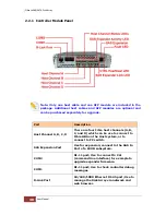
2.5.1   Expander Module Panel 


Part 

Description 

RS-232 Port 

Use to upgrade the firmware of the 
expander module. Connect the serial cable 
RJ11-to-

DB9 to your system’s serial port.


Indicator 

Color 

Description 

Activity LED 

Blinking 
Green 

Indicates the expander module is busy or 
active. 

Fault LED 

Binking 
Blue 

Indicates the expander module is faulty or 
has failed.  


RS-232 Port 

Activity LED 

Fault LED 

Summary of Contents for EP-4643S2D2-F8S6

Page 1: ...Fibre to SAS SATA RAID Subsystem User Manual Revision 1 1...

Page 2: ...g 20 1 4 Array Definition 21 1 4 1 Raid Set 21 1 4 2 Volume Set 21 1 5 High Availability 22 1 5 1 Creating Hot Spares 22 1 5 2 Hot Swap Disk Drive Support 22 1 5 3 Hot Swap Disk Rebuild 22 Chapter 2 I...

Page 3: ...rough Telnet 67 4 2 Configuration through the LCD Panel 72 4 2 1 Menu Diagram 73 4 3 Configuration through web browser based proRAID Manager 80 Chapter 5 RAID Management 82 5 1 Quick Function 82 5 1 1...

Page 4: ...t 121 5 5 4 Fibre Channel Config 123 5 5 5 EtherNet Configuration 126 5 5 6 Alert By Mail Configuration 127 5 5 7 SNMP Configuration 128 5 5 8 NTP Configuration 129 5 5 9 View Events Mute Beeper 130 5...

Page 5: ...pyright No part of this publication may be reproduced stored in a retrieval system or transmitted in any form or by any means electronic mechanical photocopying recording or otherwise without the prio...

Page 6: ...sure that the power switches are turned off Disconnect first any power connection if the power supply module is being removed from the enclosure Outlets must be accessible to the equipment All externa...

Page 7: ...2 power cords One 1 external Fibre optic cable for single RAID controller Note Two Fibre optic cables for dual RAID controllers One 1 RJ45 Ethernet cable for single RAID controller Note Two Ethernet c...

Page 8: ...Fibre to SAS SATA Disk Array 8 User Manual NOTE If any damage is found contact the dealer or vendor for assistance Key of Top Cover Screws User Manual...

Page 9: ...r with cache mirroring through dedicated high speed bus Automatic synchronization of firmware version in the dual active mode Redundant controller operation with active active and failover failback fu...

Page 10: ...AID Management Access terminal menu by telnet via a LAN port API library for customer to write its own monitor utility Field upgradeable firmware in flash ROM Firmware embedded manager via RS 232 port...

Page 11: ...1 x RJ45 Ethernet Port Battery Backup Module BBM Optional RAID level 0 1 10 1E 3 5 6 30 50 60 00 100 Single Disk and JBOD LUNs Up to 128 Hot Spare Global and Dedicated Stripe Size Up to 1024KB Cache...

Page 12: ...Disk Status Indicator Access Fail LED Backplane SAS2 SATA3 of PS Fan Modules 1100W 80plus x 2 w PFC of Fans 15 Power Requirements AC 100V 240V Full Range 15A 7 5A 47Hz 63Hz Relative Humidity 10 85 No...

Page 13: ...as large as several megabytes These stripes are then interleaved in a rotating sequence so that the combined space is composed alternately of stripes from each drive The specific type of operating en...

Page 14: ...pair of disk drives that store duplicate data but appear to the computer as a single drive Although striping is not used within a single mirrored drive pair multiple RAID 1 arrays can be striped toget...

Page 15: ...ecords Synchronized spindle drives are required for RAID 3 arrays in order to avoid performance degradation with short records RAID 5 arrays with small stripes can yield similar performance to RAID 3...

Page 16: ...l records However RAID 3 does not allow overlapping of multiple I O operations and requires synchronized spindle drives to avoid performance degradation with short records RAID 5 with a small stripe s...

Page 17: ...use of an even number of disk drives to achieve data protection while RAID 1E Enhanced Mirroring uses an odd number of drives 3 30 Combination of RAID levels 0 and 3 This level is best implemented on...

Page 18: ...This chapter describes the Fibre specific functions available in the Fibre Channel RAID controller Optional functions have been implemented for Fibre Channel operation which is only available in the...

Page 19: ...delivers a frame to a destination based on the destination address in the frame header It can be used to connect up to 16 million nodes each of which is identified by a unique world wide name WWN In...

Page 20: ...o support hot pluggability Switched Fabric Switched fabric is the highest performing device available for interconnecting large number of devices increasing bandwidth reducing congestion and providing...

Page 21: ...together in a Raid Set then the capacity of the smallest disk will become the effective capacity of all the disks in the Raid Set 1 4 2 Volume Set A Volume Set is seen by the host system as a single l...

Page 22: ...ces 1 5 2 Hot Swap Disk Drive Support The Disk Array has built in protection circuit to support the replacement of SATA II hard disk drives without having to shut down or reboot the system The removab...

Page 23: ...erms as you may encounter them later in the later chapters and sections 2 1 Main Components 2 1 1 Front View IMPORTANT When powering off the Disk Array turn off first the Main Switch and allow at leas...

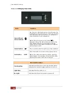
Page 24: ...ller in redundant controller mode and the other RAID controller s IP address will be shown in LCD Select button This is used to enter the option you have selected Exit button EXIT Press this button to...

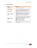
Page 25: ...mperature LED If temperature irregularities in the system occur HDD slot temperature over 65 C Controller temperature over 80 C CPU Temperature over 90 C this LED will turn RED and alarm will sound Vo...

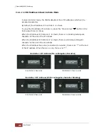
Page 26: ...ddress of Controller 1 is shown there is no blinking rectangular character at the end of the IP address When the IP address of Controller 2 is shown there is a blinking rectangular character at the en...

Page 27: ...r Color Description Activity LED Blue Blinking Indicates the disk drive is busy or being accessed Power On Fail LED Green Indicates the disk drive in this slot is good RED Indicates the disk drive in...

Page 28: ...rray 28 User Manual 2 1 2 Rear View Single Controller Dual Controller NOTE Each Power Supply Module has 1 Power Supply and 5 Fans For purpose of hardware monitoring the RAID enclosure is logically div...

Page 29: ...8 1 and Turbo Fan 06 1 Note 1 means enclosure 1 Expander Module 2 1 for Controller 2 Same function as Expander 1 1 Expander Module 1 2 for Controller 1 Monitors Enclosure 2 Disk slots 33 to 64 Power S...

Page 30: ...D There are four Fibre host channels A B C and D which can be use to connect to Fibre HBA on the Host system or to connect to FC switch SAS Expansion Port Use for expansion connect to the SAS In Port...

Page 31: ...Host Channel has linked if the Fibre HBA Card is 4GB Blink Blue Activity LED Indicates the Host Channel is busy and being accessed SAS Expander Link LED Green Indicates expander has linked SAS Expande...

Page 32: ...1100W Power Supply Fan Modules All PSFM are inserted at the rear of the chassis Front Panel Rear Side NOTE Each PSFM delivers Full Range 100V 240V 10 voltage AC electricity Each PSFM consists of 1 pow...

Page 33: ...anel and Fan 03 1 Fan 04 1 and Fan 05 1 on the rear side The second PSFM 01 2 on the right side has five fans also Fan 01 2 and Fan 02 2 on the front panel and Fan 03 2 Fan 04 2 and Fan 05 2 on the re...

Page 34: ...the PSFM has failed When the power cord connected from main power source is inserted to the AC Power Input Socket the Power Status LED becomes RED When the switch of the PSFM is turned on the LED stil...

Page 35: ...A Disk Array User Manual 35 2 4 Fan Module The 64bay Disk Array contains 15 fans NOTE 1 means enclosure 1 and 2 means enclosure 2 Fan 01 1 Fan02 1 Fan 01 2 Fan 02 2 Power Supply 01 1 Power Supply 01 2...

Page 36: ...Fibre to SAS SATA Disk Array 36 User Manual Indicator Color Description Fan Fault LED No light Indicates the fan is normal Red Indicates the turbo fan is faulty...

Page 37: ...bo Fan The turbo fan Fan 06 1 provides additional airflow inside the enclosure Turbo Fan LED Indicator Color Description Status LED Red Indicates the turbo fail is faulty NOTE The status of Turbo Fan...

Page 38: ...module monitors the following enclosure conditions temperature power supply voltage and fan speed 2 5 1 Expander Module Panel Part Description RS 232 Port Use to upgrade the firmware of the expander m...

Page 39: ...e not placed in the disk slots If all disk trays will be used to install all 64 disk drives for quicker and easier installation of disk drives in the Disk Array it is recommended to attach first each...

Page 40: ...AS disk HDD Single Controller Dual Controller SATA No need dongle board Need dongle board SAS No need dongle board No need dongle board NOTE In this model it is recommended to use 6Gb hard drive disks...

Page 41: ...Fibre to SAS SATA Disk Array User Manual 41 2 Prepare the dongle board with metal bracket 3 Connect the dongle board into the SATA disk drive...

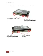
Page 42: ...User Manual 4 Place the brackets on both sides of the disk drive and secure them with screws 2 screws 6 32 UNC L 5 0mm 6 32 L 4 0mm for dongle board metal bracket 6 32 L 4 0mm for dongle board metal b...

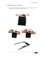
Page 43: ...to SAS SATA Disk Array User Manual 43 B HDD side brackets with dongle boards 1 Prepare the HDD side brackets Remove them from the dummy disk by pushing the upper sides of the dummy disk as shown belo...

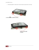
Page 44: ...Fibre to SAS SATA Disk Array 44 User Manual 2 Place the brackets on both sides of the disk drive and secure them with screws 2 screws 6 32 UNC L 5 0mm 2 screws 6 32 UNC L 5 0mm...

Page 45: ...6 2 To install a SAS disk drive Single or Dual Controller Mode or SATA disk drive Single Controller Mode in a disk tray 1 Prepare the HDD side brackets Remove them from the dummy disk by pushing the...

Page 46: ...Fibre to SAS SATA Disk Array 46 User Manual 2 Place the brackets on both sides of the disk drive and secure them with screws 2 screws 6 32 UNC L 5 0mm 2 screws 6 32 UNC L 5 0mm...

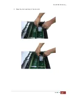
Page 47: ...Fibre to SAS SATA Disk Array User Manual 47 3 Place the drive carefully in the disk slot...

Page 48: ...Fibre to SAS SATA Disk Array 48 User Manual 4 Fix the disk drive using the disk tool that is included in the package...

Page 49: ...ctions on how to remove the power supply modules and how to remove the disk trays disk drives NOTE The sample model used in the following installation might not be the actual model for this manual NOT...

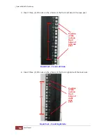
Page 50: ...f the front left side of the rack post Rack Post Front Left Side 4 Insert three 3 M5 nuts on the 2 holes of the front right side of the rack post Rack Post Front Right Side Position of M5 nuts on the...

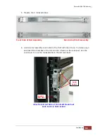
Page 51: ...sembly 6 Hold one rail assembly and install in the front left side of rack To install align and insert the 2 latches of the rail into the 2 holes on the rack post Use the Lock Lever to lock the rail a...

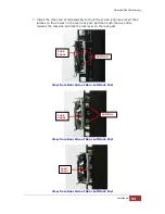
Page 52: ...l View from Front Side of Front Left Rack Post Lock Lever is Locked View from Rear Side of Front Left Rack Post 2 Latches are inserted in the 4th and 6th holes from bottom M5 nut Lower M5 Nut Lock 2 L...

Page 53: ...the 2 latches on the 2 holes on the rear rack post and then push the rail a little towards the rear side and lock the lock lever on the rack post View from Rear Side of Rear Left Rack Post View from R...

Page 54: ...step 6 to install the other rail assembly into the right front side View from Front Side of Front Right Rack Post Lock Lever is Not Locked View from Front Side of Front Right Rack Post Lock Lever is L...

Page 55: ...k Post 2 Latches are inserted in the 4th and 6th holes from bottom M5 nut 9 Repeat step 7 to install the other end of rail assembly to the rack post of rear right side View from Rear Side of Rear Righ...

Page 56: ...Fibre to SAS SATA Disk Array 56 User Manual View from Rear Side of Rear Right Rack Post View from Rear Side of Rear Right Rack Post Lock Latches Lock Lever Latches...

Page 57: ...User Manual 57 10 Pull the 2 middle rail members out from the rail assembly Middle Rail Member of Rail Assembly on Left Side of Rack View from Rear Side Rear Left Side Front Left Side Front Side Righ...

Page 58: ...iddle rails so that 2 inner rails will insert and slide easily Use hands to guide the inner rails when inserted into the middle rails Inner Rail Aligned with and Inserted into the Middle Rail Importan...

Page 59: ...blue locks on both sides of the inner rail members at the same time Then push the enclosure inwards or backwards until it goes inside the rack View from Right Side of Enclosure Blue Lock of Inner Rai...

Page 60: ...Fibre to SAS SATA Disk Array 60 User Manual View from Rear Side of Rack Cabinet Enclosure is Pushed Inwards 13 Insert the power supply modules...

Page 61: ...corner Note that the screw driver will need to pass through the corner hole of front panel for the two upper corner holes on both sides Front Left Side Front Right Side 15 Open the top cover and re i...

Page 62: ...k Array 62 User Manual 3 2 Removing the Disk Array from the Rack 1 Remove the six screws in the front corner Front Left Side Front Right Side 2 Remove the power supplies in the rear and the disk drive...

Page 63: ...Fibre to SAS SATA Disk Array User Manual 63 3 Carefully pull the subsystem 4 Push the white lock to release the subsystem from the rail...

Page 64: ...he front panel will flash blue indicating that the power cords are inserted NOTE The subsystem is equipped with redundant full range power supplies with PFC power factor correction The system will aut...

Page 65: ...sing it The main switch button will continue flashing blue until the system is finished checking each disk slot NOTE The system will initialize after turning on the Main Switch Each disk slot will be...

Page 66: ...tem to shutdown properly During this time each disk slot starting from slot 1 until slot 64 will be powered down The main switch button in the front panel will flash blue When Disk Array has totally p...

Page 67: ...port c Telnet connection via the R Link Ethernet port NOTE The Disk Array allows you to access using only one method at a time You cannot use more than one method at the same time 4 1 Configuration th...

Page 68: ...2 Enter the Disk Array s IP address Make sure the PC running the terminal emulation program can connect to the Disk Array s IP address Click Next 3 Rename the Session name if necessary Click Finish 4...

Page 69: ...isplayed Select a menu and the Password box will be shown Enter password default is 00000000 to login Keyboard Function Key Definitions A key to move to the line above Z key to move to the next line E...

Page 70: ...e Once the password has been set the user can only monitor and configure the Disk Array by providing the correct password The password is used to protect the Disk Array from unauthorized access The co...

Page 71: ...eate a customized Volume Set Physical Drive Functions View individual disk information Raid System Functions Setting the Raid system configurations More System Functions Setting the Raid system config...

Page 72: ...g the LCD panel please press first the select button Parts Function Up and Down Arrow buttons Use the Up or Down arrow keys to go through the information on the LCD screen This is also used to move be...

Page 73: ...Fibre to SAS SATA Disk Array User Manual 73 4 2 1 Menu Diagram The following menu diagram is a summary of the various configurations and setting functions that can be accessed through telnet...

Page 74: ...Fibre to SAS SATA Disk Array 74 User Manual...

Page 75: ...Fibre to SAS SATA Disk Array User Manual 75...

Page 76: ...Fibre to SAS SATA Disk Array 76 User Manual...

Page 77: ...Fibre to SAS SATA Disk Array User Manual 77...

Page 78: ...Fibre to SAS SATA Disk Array 78 User Manual...

Page 79: ...Fibre to SAS SATA Disk Array User Manual 79...

Page 80: ...troller R Link Port is 192 168 1 100 and subnet mask is 255 255 255 0 DHCP client function is also enabled by default You can reconfigure the IP Address or disable the DHCP client function through the...

Page 81: ...ring setup Raid Set Functions Create customized Raid Sets Volume Set Functions Create customized Volume Sets and allow modification of parameters of existing Volume Sets parameter Physical Drives Crea...

Page 82: ...No Volume Set capacity is set to maximum 2TB 64bit LBA This option use 16 bytes CDB instead of 10 bytes The maximum volume capacity up to 512TB For any hard disk drives working in the 4K native mode...

Page 83: ...r system maximum 32 disks per Raid Set Use the Raid Set Function and Volume Set Function if you prefer to create customized Raid Set and Volume Set NOTE In Quick Create the Raid Level options 30 50 an...

Page 84: ...ick on the Create RAID Set link A Select The Drives For RAID Set screen is displayed showing the disk drives in the system Tick the box of each disk drive that will be included in Raid Set to be creat...

Page 85: ...u can create two RAID Sets each with 32 disks to create a RAID 30 50 or 60 Volume Set 5 2 2 Delete RAID Set To delete a Raid Set click on the Delete RAID Set link A Select The Raid Set To Delete scree...

Page 86: ...which you want to expand Tick on the available disk s and check Confirm The Operation Click on the Submit button to add the selected disk s to the Raid Set NOTE Once the Expand Raid Set process has s...

Page 87: ...disk is added to a Raid Set Migrating status is displayed in the Raid Set status area of the Raid Set information Migrating status is also displayed in the Volume Set status area of the Volume Set In...

Page 88: ...Fibre to SAS SATA Disk Array 88 User Manual NOTE Cannot expand Raid Set when contains Raid30 50 60 volume...

Page 89: ...HDD state will change to Offlined Mode and the HDD Status LEDs will be blinking RED To offline a Raid Set click on the Offline RAID Set link A Select The RAID SET To Offline screen is displayed showin...

Page 90: ...RAID Set Use this function to rename a RAID Set Select the Rename RAID Set under the RAID Set Functions and then select the Select the RAID Set to rename and click Submit Enter the new name for the R...

Page 91: ...he Disk Array is powered off and one disk drive is removed or has failed in power off state and when the subsystem is powered on the Raid Set State will change to Incomplete The Volume Set s associate...

Page 92: ...ID Set link A Select The Raid Set To Activate screen is displayed showing all existing Raid Sets in the subsystem Select the Raid Set with Incomplete state which you want to activate in the Select col...

Page 93: ...using Global Hot Spare The Hot Spare disk is a hot spare on all enclosures connected in daisy chain It can replace any failed disk in any enclosure Dedicated to RaidSet The Hot Spare disk is a hot spa...

Page 94: ...te by clicking on the appropriate check box Tick on the Confirm The Operation and click on the Submit button in the screen to delete the hot spare s 5 2 9 Rescue Raid Set If you need to recover a miss...

Page 95: ...e Raid Set 5 3 1 Create Volume Set The following are the Volume Set features 1 Volume sets of different RAID levels may coexist on the same Raid Set 2 Up to 128 Volume Sets in a Raid Set can be create...

Page 96: ...ater Two TB Volume Support will be automatically provided in the screen as shown in the example above There are three options to select No 64bit LBA and 4K Block No Volume Set size is set to maximum 2...

Page 97: ...hrough data are both written to the cache and the disk s before the write I O is acknowledged as complete Write Back when data is written to cache the I O is acknowledged as complete and some time lat...

Page 98: ...ents of the present invention described above can be implemented within a Switch for FC Arbitrated Loop LUN Base The base LUN number Each LUN Base supports 8 LUNs LUN Each Volume Set must be assigned...

Page 99: ...de in the creation and then click on the Submit button NOTE When creating Raid 30 50 60 Volume set you need to create first the Raid Sets Up to 8 Raid Sets maximum is supported in Raid 30 50 60 All Ra...

Page 100: ...lete Volume Set link The Select The Volume Set To Delete screen will show all available Raid Sets Tick on a Raid Set and check the Confirm The Operation option and then click on the Submit button to s...

Page 101: ...ick on the Modify Volume Set link 2 Tick from the list the Volume Set you want to modify Click on the Submit button The following screen appears To modify Volume Set attribute values select an attribu...

Page 102: ...to enlarge the Volume Set size or create another Volume Set Use the Modify Volume Set function to expand the Volume Set capacity Select the Volume Set and move the cursor to the Volume Set Capacity it...

Page 103: ...Migration Migration occurs when a Volume Set migrates from one RAID level to another a Volume Set stripe size changes or when a disk is added to a Raid Set Migrating status is displayed in the Volume...

Page 104: ...Set Only RAID levels with parity redundant data such as RAID Levels 3 5 6 30 50 and 60 support this function To perform Check Volume Set function 1 Click on the Check Volume Set link 2 Tick from the l...

Page 105: ...tarted The checking percentage can also be viewed by clicking on RaidSet Hierarchy in the Information menu NOTE The result of Check Volume Set function is shown in System Events Information and Volume...

Page 106: ...the Submit button Scheduler Disabled 1Day For Testing 1Week 2Weeks 3Weeks 4Weeks 8Weeks 12Weeks 16Weeks 20Weeks and 24Weeks Check After System Idle No 1 Minute 3 Minutes 5 Minutes 10 Minutes 15 Minut...

Page 107: ...Raid Set The disk is available to the host as an individual disk It is typically used on a system where the operating system is on a disk not controlled by the RAID firmware To create pass through di...

Page 108: ...se LUN on an existing Pass Through Disk To modify the Pass Through drive attribute from the Pass Through drive pool click on the Modify a Pass Through Disk link The Select The Pass Through Disk For Mo...

Page 109: ...the delete action 5 4 4 Clone Disk Instead of deleting a RAID set and recreating it with larger disk drives the Clone Disk function allows the users to replace larger disk drives to the RAID set that...

Page 110: ...peat above procedures to define another clone pair 4 Select clone type The pair number for both the Clone Source and the Clone Target will be indicated in the screen Tick on the Confirm The Operation...

Page 111: ...gical drives is copied onto the new drives and then the original members are marked as Offlined 5 4 4 2 Clone Only The stand by disk will clone the logical drives without substituting it The status of...

Page 112: ...Failed Disk It forces the current failed disk in the system to be back online Activate Failed Disk function has no effect on the removed disks because a removed disk does not give the controller a ch...

Page 113: ...ication screen appears Tick on the enclosure from the list of enclosures then click on the Submit button to identify the selected enclosure All disk drives LEDs in an enclosure will flash when a parti...

Page 114: ...ve is selected using the Identify Drive function the Status LED of the selected disk drive will be blinking To identify a selected drive from the drives pool click on the Identify Drive link The Selec...

Page 115: ...ation The RAID Subsystem allows user to choose the background task priority High 80 Medium 50 Low 25 and Ultra Low 5 to balance between background task process and Volume Set access For high RAID Subs...

Page 116: ...RAID state will change to Degraded Mode while it powers on Disk Write Cache Mode The Disk Array supports Disk Write Cache Mode options Auto Enabled and Disabled If the Disk Array has BBM battery back...

Page 117: ...on The capacity of the disk drive is not truncated Smart Option For HDD This option is used to increases the reliability of SSDs HDDs by automatically copying data from a drive with potential to fail...

Page 118: ...nts the RAID controller from dropping the drive from the array during this period Default value is manufacture setting You can select between 5 6 and 7 second This feature is to setup the HDD internal...

Page 119: ...Default value is Auto Controller will base on the HDD number to set the amount of Read Ahead value You can select between 512KB 16MB Number of AV Stream RAID controllers are required to have not only...

Page 120: ...HDD Speed This function is used to set the Hitachi SATA HDD Speed WDC SATA HDD Speed This function is used to set the WD SATA HDD Speed Seagate SATA HDD Speed This function is used to set the Seagate...

Page 121: ...has three options MAID Levels Level 1 Place idle drives in Lower Power Mode where the drives heads are unloaded Level 2 Place idle drives in Low RPM Mode where drives heads are unloaded and slows dow...

Page 122: ...system waiting time for HDD spin up The values can be selected from 7 to 120 seconds NOTE To verify if the disk drive you use supports MAID or APM select RaidSet Hierarchy and click the disk drive E...

Page 123: ...h FC port has its unique WWPN which is also factory assigned Usually the WWNN WWPN tuple is used to uniquely identify a port in the Fabric Channel Speed Each FC port speed can be configured either as...

Page 124: ...n Note that current topology is shown as None when no successful connection is made for the channel Hard Loop ID This setting is effective only under Loop topology When enabled you can manually set th...

Page 125: ...s Disk Array is connected to Channel Speed setting Channel Topology setting 8Gb FC switch 8Gb Fabric 4Gb FC switch 4Gb Fabric 8Gb FC HBA no switch 8Gb Loop 4Gb FC HBA no switch 4Gb Loop Fabric topolog...

Page 126: ...EtherNet Configuration link under the System Controls menu The Disk Array EtherNet Configuration screen will be shown Set the desired configuration Once done tick on the Confirm The Operation and clic...

Page 127: ...be emailed to the email recipient s that a problem has occurred Events are classified into 4 levels Urgent Serious Warning and Information NOTE If Event Notification by email is enabled every 30 of e...

Page 128: ...ess box the IP address of the host system where SNMP traps will be sent The SNMP Port is set to 162 by default SNMP System Configuration Community Type the SNMP community The default is public 1 sysCo...

Page 129: ...TP Server IP Address to enable the Disk Array to synchronize with it To set the NTP function move the cursor to the main menu and click on the NTP Configuration link The Disk Array s NTP Configuration...

Page 130: ...formation move the mouse cursor to the System Controls menu and click on the View Events Mute Beeper link The Disk Array s System Events Information screen appears The System Events Information screen...

Page 131: ...te Test Event If you want to generate test events move the cursor bar to the main menu and click on the Generate Test Event Link Tick on the Confirm The Operation and click on the Submit button Then c...

Page 132: ...Fibre to SAS SATA Disk Array 132 User Manual 5 5 11 Clear Event Buffer Use this feature to clear the Disk Array s System Events Information buffer...

Page 133: ...u from the initial screen The Disk Array will automatically go back to the initial screen when it does not receive any command after sometime To disable the password enter only the original password i...

Page 134: ...AID Controller This is used to flush the data from the cache memory and is normally done before powering off the system power switch After shutting down the controller and still want to use the Disk A...

Page 135: ...Fibre to SAS SATA Disk Array User Manual 135 5 5 15 Restart Controller Use this function to restart the RAID Controller This is normally done after upgrading the controller s firmware...

Page 136: ...s configuration and information Select the RAID Set Hierarchy link from the Information menu to display the Raid Set Hierarchy screen To view the Raid Set information click the Raid Set link from the...

Page 137: ...iting customer data The read only palimpsest benchmark of the disk is shown in the device information If the value drops below the normal curve something may be wrong with the disk User can use Set Di...

Page 138: ...mpsest benchmark on a hard drive The length time of firmware takes to complete the drive test depends on its size To view the Volume Set information click the Volume VOL link from the Raid Set Hierarc...

Page 139: ...SAS Address Component Vendor Component ID Enclosure number Number of Phys and Attached Expander information will be shown User can click on controller and SAS expander item on the SAS Chip Information...

Page 140: ...Fibre to SAS SATA Disk Array 140 User Manual...

Page 141: ...The following are the states under Dual Controller State Dual Controller State Description Single Controller is running at Single Mode Other Controller Added The other Controller is added and waiting...

Page 142: ...n The following are the states of Battery Backup Module BBM State Description Not Installed BBM is not installed xx The percentage of battery remaining Charged 100 BBM is completely charged Failed BBM...

Page 143: ...hold values are surpassed warning messages will be indicated through the LCD LED and alarm buzzer Item Warning Condition CPU Temperature 90 Celsius Controller Board Temperature 80 Celsius HDD Temperat...

Page 144: ...any Fibre cable from the controller module and then remove the Controller Module from the slot 4 Remove the memory module from the RAM socket of the RAID controller by pressing the ejector clips unti...

Page 145: ...me and VVV refers to the firmware version README TXT It contains the history information of the firmware change Read this file first before upgrading the firmware These files must be extracted from th...

Page 146: ...connect to Disk Array using Telnet open Terminal Emulation program example CRT 6 1 Refer to Section 4 1 for sample step to enable Telnet connection via CRT program 2 After successful connection select...

Page 147: ...le xxxx vvv yyyyyyyy bin and click Add Then click OK NOTE The BOOT firmware file xxxxBOOT vvv yyyyyyyy bin must be upgraded first Then repeat the steps to upgrade the firmware file xxxx vvv yyyyyyyy b...

Page 148: ...Fibre to SAS SATA Disk Array 148 User Manual 6 A message Update The Firmware will be displayed Select Yes 7 Select Yes again 8 Message will show Start Updating Firmware Please Wait...

Page 149: ...isk Array User Manual 149 9 Message will show Firmware has been updated successfully 10 The RAID Controller must be restarted in order for the new firmware to take effect 11 Select Restart Controller...

Page 150: ...Fibre to SAS SATA Disk Array 150 User Manual 12 Select Yes again to confirm The RAID controller will restart...

Page 151: ...e click the Upgrade Firmware link under System Controls menu The Upgrade The Raid System Firmware Or Boot Rom screen appears 2 Click Browse Look in the location where the firmware file was saved Selec...

Reviews: