background image


iSCSI-to-SATA II RAID Subsystem


14 

User Manual 


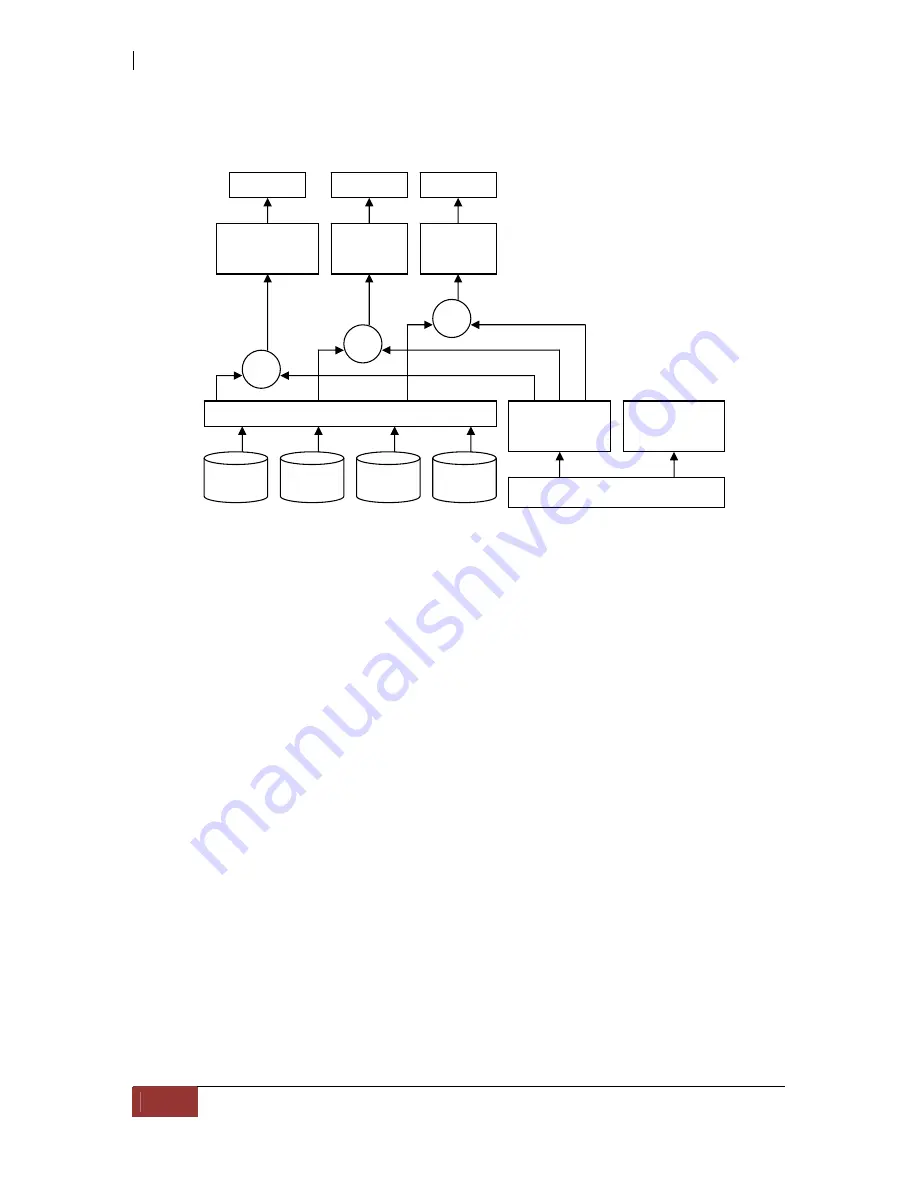
1.5   Volume Relationship Diagram 


This diagram shows how the volume structure of the iSCSI RAID subsystem is 
designed. It describes the relationship of RAID components. One RG (RAID group) 
consists of a set of VDs (Virtual disk) and owns one RAID level attribute. Each RG can 
be divided into several VDs. The VDs in one RG share the same RAID level, but may 
have different volume capacity. Each VD will be associated with the Volume Cache 
(portion of cache memory) to execute the data transaction. LUN (Logical Unit Number) 
is a unique identifier assigned to every VD, and users access the LUN through SCSI 
commands. 


RG

PD 2 

PD 3 

DS 

PD 1 

VD 1 

VD 2 

VD 3 

RAM (cache memory) 

Volume 

Cache 

System 

Cache 

+

LUN 1

LUN 2

LUN 3

+

+

Summary of Contents for iSCSI-to-SATA II RAID Subsystem

Page 1: ...iSCSI to SATA II RAID Subsystem User Manual Revision 1 0 P N PW0020000000374...

Page 2: ...ing the iSCSI RAID Subsystem to Your Network 20 2 5 Powering On 20 2 6 Installing Hard Drives 21 2 7 iSCSI Introduction 22 2 8 Management Methods 24 2 8 1 Web GUI 24 2 8 2 Serial Monitor Port 25 2 8 3...

Page 3: ...itor 67 3 7 3 Hard Drive S M A R T Function 68 3 7 4 UPS 69 3 8 System Maintenance 70 3 8 1 System Information 70 3 8 2 Upgrade 71 3 8 3 Reset to Default 71 3 8 4 Config Import Export 72 3 8 5 Event L...

Page 4: ...the highest industry standards and the best data solution for small or medium business users Unparalleled Performance Front end 2 x 1Gb full iSCSI offload System architecture provides high data bandwi...

Page 5: ...6 10 and JBOD Global hot spare disks Write through or write back cache policy for different application usage Supports greater than 2TB per Virtual Disk LUN RAID level migration Online volume expansi...

Page 6: ...sk insertion removal detection Hot swap drive trays Five 5 1 inch trays Auto volume rebuild Host access control Read Write Read Only Array roaming Supports CHAP authentication Audible alarm Jumbo fram...

Page 7: ...ow RAID width copy and row are used to describe one RG E g 1 One 4 disk RAID 0 volume RAID width 4 RAID copy 1 RAID row 1 2 One 3 way mirroring volume RAID width 1 RAID copy 3 RAID row 1 3 One RAID 10...

Page 8: ...virtual disks SCSI Small Computer Systems Interface iSCSI Internet Small Computer Systems Interface FC Fibre Channel S M A R T Self Monitoring Analysis and Reporting Technology WWN World Wide Name HBA...

Page 9: ...r as large as several megabytes These stripes are then interleaved in a rotating sequence so that the combined space is composed alternately of stripes from each drive The specific type of operating e...

Page 10: ...a pair of disk drives that store duplicate data but appear to the computer as a single drive Although striping is not used within a single mirrored drive pair multiple RAID 1 arrays can be striped tog...

Page 11: ...an satisfy only one I O request at a time RAID 3 delivers the best performance for single user single tasking environments with long records Synchronized spindle drives are required for RAID 3 arrays...

Page 12: ...sed RAID 3 can be used to speed up data transfer and provide fault tolerance in single user environments that access long sequential records However RAID 3 does not allow overlapping of multiple I O o...

Page 13: ...copies of the disk N 3 Data is striped across several physical drives Parity protection is used for data redundancy 3 5 Data is striped across several physical drives Parity protection is used for dat...

Page 14: ...owns one RAID level attribute Each RG can be divided into several VDs The VDs in one RG share the same RAID level but may have different volume capacity Each VD will be associated with the Volume Cac...

Page 15: ...carton may indicate that the contents of the carton are damaged If any damage is found do not remove the components contact the dealer where you purchased the subsystem for further instructions 2 2 Un...

Page 16: ...iSCSI to SATA II RAID Subsystem 16 User Manual 2 3 Identifying Parts of the iSCSI RAID Subsystem The illustrations below identify the various parts of the subsystem 2 3 1 Front View...

Page 17: ...Drive Tray is unlocked Lock and unlock the Drive Trays by using a flat head screw driver Tray Lever Use this to pull out the disk tray HDD Status Indicator Every Drive Tray contains two LEDs for disp...

Page 18: ...iled LCD Display This displays the current IP address and the model name or the iSCSI RAID subsystem LCD Control Module LCM Use the function keys to navigate through the menu options available in the...

Page 19: ...h an RS232 serial port allowing you to connect a PC or terminal using the null modem cable phone jack to DB9 R Link Port Remote Link through RJ 45 Ethernet for remote management The subsystem is equip...

Page 20: ...CSI unit Insert the other end into a Gigabit BASE T Ethernet connection on your network hub or switch You may connect the other network port LAN2 if needed For remote management of the iSCSI RAID subs...

Page 21: ...the Drive Carriers by using a flat head screw driver The Lock Grooves are located on the carrier open button a Press the Carrier Open Button and the drive carrier handle will flip open b Pull out an e...

Page 22: ...Microsoft Windows Linux Solaris etc within the SAN network IP SANs also include mechanisms for security data replication multi path and high availability Storage protocol such as iSCSI has two ends in...

Page 23: ...loads details aspx FamilyID 12cb3c1a 15d6 4585 b385 befd1319f825 DisplayLang en Please refer to Appendix D for Microsoft iSCSI initiator installation procedure 2 Linux iSCSI initiator is also availabl...

Page 24: ...ent function is enabled in the iSCSI RAID subsystem but DHCP server cannot be located or DHCP service is not available the subsystem uses zero config Zeroconf to get an IP address Example On LCD Displ...

Page 25: ...Control Secure Shell SSH secure shell is required for the iSCSI RAID subsystem to remote login The SSH client software is available at the following web site SSHWinClient WWW http www ssh com Putty W...

Page 26: ...IP for example 192 168 10 50 from DHCP server and iSCSI model name 192 168 10 50 iSCSI Model Name Press ENT the LCM functions System Info Alarm Mute Reset Shutdown Quick Install Volume Wizard View IP...

Page 27: ...peration in web UI Volume Wizard Smart steps to create a volume Please refer to next chapter for operation in web UI View IP Setting Display current IP address subnet mask and gateway Change IP Config...

Page 28: ...AID 3 RAID 5 RAID 6 RAID 0 1 Use default algorithm Volume Size xxx GB Apply The Config cYes Nod IP Config Static IP IP Address 192 168 010 050 IP Subnet Mask 255 255 255 0 View IP Setting IP Gateway 1...

Page 29: ...essfully 2 The system buzzer alarms continuously when an error level event happens The alarm will be stopped after mute 3 The alarm will be muted automatically when the error situation is resolved E g...

Page 30: ...Delete CHAP account Create Delete Volume configuration Volume create wizard Step 1 Step 2 Step 3 Step 4 Confirm Physical disk Set Free disk Set Global spare Set Dedicated spare Set property More info...

Page 31: ...lt IP setting is DHCP open web browser and enter http 192 168 10 50 Please check the DHCP address first on LCM The Login Page will be displayed Enter a user name and password To login as admin with fu...

Page 32: ...l After login you can choose a menu or function on the left side screen 3 2 1 Language Before clicking the Login button you can change the GUI language if needed There are 5 options to select English...

Page 33: ...presents RAID failure happening 2 Temperature light Green is normal Red represents abnormal temperature 3 Voltage light Green is normal Red represents abnormal voltage status 4 UPS light Green is norm...

Page 34: ...are already used in another RG Quick install can not be used because the function is valid only when all physical disks in the system are free Step 1 Select Quick install then choose the RAID level Af...

Page 35: ...SCSI to SATA II RAID Subsystem User Manual 35 3 4 System Configuration System configuration is designed for setting up the System setting IP address Login setting Mail setting and Notification setting...

Page 36: ...System setting to change system name and date Default system name is the model name e g DP 504 G1A3 Check Change date and time option to set up the current date time and time zone before using or sync...

Page 37: ...o change the IP address for remote administration usage There are 2 options DHCP Get IP address from DHCP server or Static static IP The default setting is DHCP enabled User can change the HTTP HTTPS...

Page 38: ...tions are 1 Disable 2 5 minutes 3 30 minutes 4 1 hour The system will log out automatically when user is inactive for a period of time 2 Login lock Disable Enable When the login lock is enabled the sy...

Page 39: ...ifications Some mail servers would check Mail from address and need authentication for anti spam Please fill the necessary fields and select Send test mail to check whether the email works fine User c...

Page 40: ...ssenger not MSN and alerts via syslog protocol and set event log filter SNMP allows up to 3 SNMP trap addresses Default community is set to public User can choose the event log levels the default sett...

Page 41: ...settings only the WARNING and ERROR event logs are enabled Using System log server user can choose the facility and the event log level The default port of syslog is 514 The default setting enables ev...

Page 42: ...of the iSCSI RAID subsystem and setup iSNS IP for iSNS Internet Storage Name Service service iSNS protocol allows automated discovery management and configuration of iSCSI devices on a TCP IP network...

Page 43: ...e to the gray button of LAN port click IP settings for iSCSI ports There are 2 selections DHCP Get IP address from DHCP server or Static Static IP address Default gateway Default gateway can be change...

Page 44: ...nt a key to be used for encrypting the username and password CHAP enables the username and password to transmitting in an encrypted form for protection To use CHAP authentication please follow the ste...

Page 45: ...nnection information including the following items 1 Host Initiator Name 2 Error Recovery Level 3 Error Recovery Count 4 Detail of Authentication status and Source IP port number Move the mouse pointe...

Page 46: ...authentication To setup CHAP account please follow these steps 1 Click Create 2 Enter account name in User box and type the secret in Secret and Confirm boxes 3 Click Confirm The CHAP account will be...

Page 47: ...Configuration Volume configuration is designed for setting up the volume configuration which includes Volume create wizard Physical disk RAID group Virtual disk and Logical unit NOTE Snapshot functio...

Page 48: ...t gives user 1 Biggest capacity of RAID level for user to choose and 2 The fewest disk number for RAID level volume size E g user chooses RAID 5 and the controller has 3 200G and 1 120G HDDs inserted...

Page 49: ...Decide VD size User can enter a number less or equal to the default number Then click Next Step 4 Confirm page Click Confirm if all settings are correct Then a VD will be created It s done You can sta...

Page 50: ...tive function s will show in gray color For example set PD slot number 4 to dedicated spare disk Step 1 Move the mouse pointer to the gray button of PD Slot 4 then select Set Dedicated spare It will l...

Page 51: ...e hard drive is failed Error Alert S M A R T error alert Read Errors the hard drive has unrecoverable read errors Usage RD RAID Disk This hard drive has been set to RAID FR FRee disk This hard drive i...

Page 52: ...d drive as global spare of all RGs Set Dedicated spares Set the hard drive as dedicated spare of selected RG Set property Change the status of write cache and standby Write cache options Enabled Enabl...

Page 53: ...mple of how to create a RG Step 1 Click Create enter the RAID Group Name choose a RAID level click Select PD to select Physical Disks Then click Next Step 2 Confirm page Click Confirm if all settings...

Page 54: ...n RAID group VD The number of virtual disks in RAID group Status The status of RAID group Online the RAID group is online Offline the RAID group is offline Rebuild the RAID group is being rebuilt Migr...

Page 55: ...be executed when RG status is online This is for online roaming purpose Scrub Scrub a RAID group It s a parity regeneration function It supports RAID 3 5 6 only Delete Delete a RAID group Set disk pr...

Page 56: ...is an example of how to create a VD Step 1 Click Create enter the Virtual Disk Name choose RG name change Capacity if necessary select Stripe height Block size Read Write cache mode volume Priority a...

Page 57: ...nline the Virtual disk is online Offline the Virtual disk is offline Initiating the Virtual disk is being initialized Rebuild the Virtual disk is being rebuilt Migrate the Virtual disk is being migrat...

Page 58: ...neration function It supports RAID 3 5 6 only Delete Delete a Virtual disk Set property Change the VD name right priority and bg rate Right options WT Write Through WB Write Back RO Read Only Priority...

Page 59: ...ch means every host can access the volume Choose LUN number and permission and click Confirm LUN operations description Attach Attach a logical unit number to a Virtual disk Detach Detach a logical un...

Page 60: ...eated after system boots up automatically So no action is needed to set CV Then set a global spare disk Eventually delete all of them Step 1 Create RG RAID group To create the RAID group please follow...

Page 61: ...ease follow these steps 1 Select Volume configuration Virtual disk 2 Click Create 3 Input a VD name choose a RG Name and enter a size of VD decide the stripe high block size read write mode and set pr...

Page 62: ...t to the VD number click Attach LUN 2 In Volume configuration Logical unit click Attach The procedures are as follows 1 Select a VD 2 Input Host name which is a FC node name for access control or fill...

Page 63: ...button next to the PD slot click Set Global spare 3 GS icon is shown in Usage column Step 5 Done Host initiator can connect to the LUN s and use as disk s To delete VD and RG please follow the steps...

Page 64: ...n RAID group 2 Select a RG which has no VD related on this RG otherwise the VD s on this RG must be deleted first 3 Move the mouse pointer to the gray button next to the RG number click Delete 4 There...

Page 65: ...an sensors power sensors and LED status And due to the hardware characteristics are different among these sensors for different sensors they have different polling intervals Below is the detail about...

Page 66: ...re Services one of the enclosure management standards Use SES config function to enable or disable the management of SES To enable SES 1 Click Enable 2 Enter Host name iSCSI node name Click Confirm 3...

Page 67: ...SCSI RAID subsystem use multiple condition judgments for Auto shutdown below is the detail of when the Auto shutdown will be triggered 1 There are 3 sensors placed on the controller for temperature ch...

Page 68: ...se to be out of tolerance The advanced notice of possible hard drive failure can allow users to back up hard drive or replace the hard drive This is much better than hard drive crash when it is writin...

Page 69: ...for APC None for other vendors or no UPS Shutdown Battery Level When below the setting level system will shutdown Setting level to 0 will disable UPS Shutdown Delay s If power failure occurred and sys...

Page 70: ...ry default to reset all controller configuration values to factory settings Import and export to import and export all controller configuration Event log to view system event log to record critical ev...

Page 71: ...on first Click Cancel to export system configuration in advance or click OK to start to upgrade firmware When upgrading there is a progress bar running After finished upgrading the system must reboot...

Page 72: ...avoid conflict or data deletion between two controllers For example if one controller already has existing valuable data in the disks and user may forget to overwrite it Use import could return to ori...

Page 73: ...elName Date Time txt e g log DP 504 G1A3 20090507 190659 txt Click Clear button will clear event log Click Mute button will stop alarm if system alerts The event log is displayed in reverse order whic...

Page 74: ...uttons Before power off it is better to execute Shutdown to flush the data from cache to physical disks The step is necessary for data protection 3 9 Logout For security reason Logout function will al...

Page 75: ...t belonging to any existing RG it would be FR Free disk and the system will start Auto Rebuild function c If user only removes the failed disk and plugs the same failed disk in the same slot again the...

Page 76: ...ith parity on the dedicated disk RAID 3 allows one hard drive failure or unplugging RAID 5 Striping with interspersed parity over the member disks RAID 5 allows one hard drive failure or unplugging RA...

Page 77: ...p page When doing migration to lower RAID level such as the original RAID level is RAID 6 and user wants to migrate to RAID 0 system will evaluate whether this operation is safe or not and appear a me...

Page 78: ...G must be larger or equal to the original RG It does not allow expanding the same RAID level with the same hard disks of original RG The operation is not allowed when RG is being migrated System would...

Page 79: ...to the VD number click Extend 3 Change the size The size must be larger than the original and then click Confirm to start extension 4 Extension starts If VD needs initialization it will display Initia...

Page 80: ...ther The configuration of both RG and VD will be kept but LUN configuration will be cleared in order to avoid conflict with system 2 4 6 Support Microsoft MPIO and MC S MPIO Multi Path Input Output an...

Page 81: ...C Reg with Hynix Unigen UG7128D7488LN GJF 1GB DDR 400 ECC with Hynix Unigen UG7128D7588LZ GJF 1GB DDR 400 ECC Reg with Hynix Unigen UG7128D7588LZ GJF 1GB DDR 400 ECC Reg with Elpida Unigen UG732D6688K...

Page 82: ...e contact your local distributor iSCSI HBA card Vendor Model HP NC380T PCI Express Gigabit 2 ports TCP IP offload iSCSI offload QLogic QLA4010C PCI X Gigabit 1 port TCP IP offload iSCSI offload QLogic...

Page 83: ...B 7200RPM SATA 1 5Gb s 8M NCQ Seagate Barracuda 7200 9 ST3500641AS 500GB 7200RPM SATA 3 0Gb s 16M NCQ Seagate Barracuda 7200 11 ST31000340AS 1000GB 7200RPM SATA 3 0Gb s 32M NCQ Seagate NL35 ST3400633N...

Page 84: ...NG Power detect PSU signal detection number INFO Fan work Fan number is restored to work ERROR Fan warning Fan number is out of work INFO Fan installed Fan number is installed ERROR Fan not present Fa...

Page 85: ...VD created VD name has been created INFO VD creation failed Failed to create VD name INFO VD deleted VD name has been deleted INFO VD renamed Name of VD name has been renamed to name INFO Read only ca...

Page 86: ...e read error occurred Recoverable read error occurred at LBA address address of VD name WARNING Recoverable write error occurred Recoverable write error occurred at LBA address address of VD name ERRO...

Page 87: ...od INFO BBM is charging Battery backup module is charging WARNING BBM is failed Battery backup module is failed INFO BBM Battery backup feature is item JBOD events Level Type Description INFO Disk ins...

Page 88: ...name System maintenance events Level Type Description INFO System shutdown System shutdown INFO System reboot System reboot INFO FW upgrade start Firmware upgrade start INFO FW upgrade success Firmwa...

Page 89: ...he steps to setup Microsoft iSCSI Initiator Please visit Microsoft website for latest iSCSI initiator The following setup may not use the latest Microsoft iSCSI initiator 1 Run Microsoft iSCSI Initiat...

Page 90: ...iSCSI to SATA II RAID Subsystem 90 User Manual 4 Click OK 5 Click Targets...

Page 91: ...iSCSI to SATA II RAID Subsystem User Manual 91 6 Click Log On Check Enable multi path if running MPIO 7 Click Advance if CHAP information is needed 8 Click OK The status would be Connected...

Page 92: ...iSCSI to SATA II RAID Subsystem 92 User Manual 9 Done it can connect to an iSCSI disk The following procedure is to log off iSCSI device a Click Details...

Page 93: ...st server is not LBA Logical Block Addressing 64bit supported For detail installation steps please refer to following steps below Step 1 Configure target 1 Prepare large capacity hard drivers where th...

Page 94: ...from the link below http www microsoft com downloads details aspx FamilyID 12cb3c1a 15d6 4585 b385 befd1319f825 DisplayLang en Step 3 Initialize Format Mount the disk 1 Go to Start Control Panel Comp...

Page 95: ...iSCSI to SATA II RAID Subsystem User Manual 95 4 Format the disk 5 Done 6 The new disk is ready to use the available size 2 72TB...

Page 96: ...ARNING If user setups 512B block size for VD and the host server OS is 32bit in the last step of formatting disk user will find OS cannot format the disk sector after 2048GB 2TB 7 Wrong setting result...

Page 97: ...following 1 Create RG VD and then attach LUN 2 Add the first Target Portal on Microsoft iSCSI initiator 3 Add the second Target Portal on Microsoft iSCSI initiator 4 Logon 5 Enable Enable multi path c...

Page 98: ...iSCSI initiator For MC S there is only ONE Target Portals in the Discovery tab 3 Logon 4 Then click Advanced 5 Select the first Source IP and Target Portal to iSCSI data port 1 Then click OK 6 After...

Reviews: