27
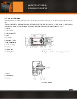
The push button station of Model CDI electric hoist provides such buttons.
Stop(off),Start(on),Up(Δ),Down( ),Left(<J ),right([>),F),Backward(0).
The same of Model MDI provides: Stop(off), Start(on),Creep Up(Δ),Fast Up(Δ),Fast Down( ),Creep
Down( ),Left( <J ),Right([> ),F),Backward(0). The F)& Backward(0) are prepared for Bridge Crane moving. The
Electrical Devices is designed possessing both mechanical and electrical interlock.
The power lead-in can adopt cable, sliding bar or other proper methods.
When cable is used, the Cable Lead-in Device 1a(1) will be mounted to fix cable for the Control Cabinet receiving power.
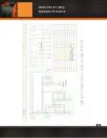
The principle of electric control. On pushing down the button Start (on), the KO AC contactor acts in self-security mode so as to pro-
vide power for other contactors. When the power in accident shot-cut, the KO contactor losses electricity, simultaneously the main
source is cut off. Since the hoist is in usage and hung in air, it is not convenient for operator to treat, the protection of shot-cut does
not provided unless specially required by customer.
When the hoist need to work, push the button of selected direction, connect related contactors to master the action of hoist, mean-
while the control loop of opposite contactors Will be cut off to realize electric interlock. When the pushed button is released, the
contactor will release too, the hoist stop acting.
Push down the Stop(off) button when job finished or in emergency, the KO contactor losses electricity leading power off.
Δ
Δ
Δ
MAIN STRUCTURE &
RUNNING PRINCIPLE
Summary of Contents for PWMD Series
Page 1: ...1 PWMD and PWMDF SERIES User Manual and Security Warnings...
Page 17: ...17 MAIN STRUCTURE RUNNING PRINCIPLE...
Page 18: ...18 MAIN STRUCTURE RUNNING PRINCIPLE...
Page 19: ...19 MAIN STRUCTURE RUNNING PRINCIPLE...
Page 20: ...20 MAIN STRUCTURE RUNNING PRINCIPLE...
Page 21: ...21 MAIN STRUCTURE RUNNING PRINCIPLE...
Page 22: ...22 MAIN STRUCTURE RUNNING PRINCIPLE...
Page 28: ...28 MAIN STRUCTURE RUNNING PRINCIPLE...
Page 29: ...29 MAIN STRUCTURE RUNNING PRINCIPLE...
Page 33: ...33 PRECAUTION AND TROUBLE SHOOTING...
Page 66: ...66 b PWMD3T24M TECHNICAL SPECIFICATIONS...
Page 67: ...67 c PWMD5T24M TECHNICAL SPECIFICATIONS...
Page 68: ...68 d PWMD10T24M TECHNICAL SPECIFICATIONS...
Page 69: ...69 e PWMD16T24M TECHNICAL SPECIFICATIONS...
Page 70: ...70 f PWMD20T24M TECHNICAL SPECIFICATIONS...
Page 71: ...71 g PWMD25T18M TECHNICAL SPECIFICATIONS...
Page 72: ...72 h PWMD50T12M TECHNICAL SPECIFICATIONS...
Page 73: ...73 i PWMD50T20M TECHNICAL SPECIFICATIONS...
Page 74: ...74 j PWMDF3T24M TECHNICAL SPECIFICATIONS...
Page 75: ...75 k PWMDF5T24M TECHNICAL SPECIFICATIONS...
Page 76: ...76 l PWMDF10T24M TECHNICAL SPECIFICATIONS...
Page 77: ...77 m PWMDF16T24M TECHNICAL SPECIFICATIONS...
Page 78: ...78 n PWMDF20T24M TECHNICAL SPECIFICATIONS...
Page 79: ...79 o PWMDF25T18M TECHNICAL SPECIFICATIONS...
Page 80: ...80 p PWMDF32T18M TECHNICAL SPECIFICATIONS...
Page 81: ...81 q PWMDF50T12M TECHNICAL SPECIFICATIONS...
Page 82: ...82 r PWMDF50T20M TECHNICAL SPECIFICATIONS...
Page 84: ...84...


