30
3. INSTALLATION AND ADJUSTMENT
3.1 INSTALLATION
3.1.1 When the hoist is shipped to the installation site, to care that no damage has been done during the transportation.
3.1.2 The hoist runs with the fixed and standard rail(see Table 1a,1b). In order to match the variable I beam rails, user should select
standard rail referring the tables or design by themselves ( the rail must be in compliance with related standard).While installing,
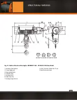
the width between traversing wheels can be adjusted with Gaskets P (See Fig.1). A clearance of 4mm~ 5mm on each side should be
maintained between the wheel edges and bottom flange of the I beam during the adjustment.
3.1.3 Stop pins or elastic buffers should be installed on both ends of the rail in order to avoid the hoist from derailing and damaging
the body by impacting.
3.1.4 A protective earth should be laid on the I beam or the structure connected with hoist. Either φ4mm ~ φ5mm bare copper wire
or any metal conductor with the section not less than 25mm2 can be used.
3.1.5 After the completion of the installation of all the electric appliances, the earth insulation resistance to all the power loop and
control loop should not be less than 1.5MΩ.
3.2 ADJUSTMENT
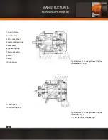
3.2.1 Fig.4 shows the hoisting motor structure of electric hoist model CDI 0.5t-5t. When adjusting, first loosen the screw (1), rotate
clockwise the locking nut (2) so as to increase the pressure on the spring (7) and gain a greater braking torque, then tighten the
screw (1). shortening the slide-down distance.
Watch carefully the leap clearance of motor shaft when starting and stopping the motor repeatedly (or press the shaft end of mo-
tor with force to cause it shifting). Generally speaking, the leap clearance of 1.5mm is recommended; rotate in counter clockwise
the locking nut (2) which has 1.5mm screw can reduce the leap clearance. In case the slide-down distance of hoist still exceeds the
specifications after the adjustment, eliminate the troubles one by one in accordance with Table 5 “TROUBLE-SHOOTING” in item 2.
3.2.2 Fig. 5 shows the motor of the electric hoist model CDI 10t. The adjusting method for it is same in principle as mentioned above,
instead of the locking nut (2) should be rotated in contrary direction.
3.2.3 Adjustment can be made to motor brake according to the following description. For model CDI, when the braking lining is won
out or damaged, replacement should be made. While replacing, the braking lining must be pressed tighten into the fan brake wheel.
The internal cone surface of the braking lining should be machined and ground carefully to have an excellent connection with the
conic surface of the rear cover so as to ensure a reliable braking. For adjustment to Model MDI, please disassemble the dust-proof
cover at the end of big motor and do the adjustment as per previous description. And the same can be done to the small motor as
per 3.2.1.
3.2.4 The adjusting method of the traversing motor is the same as that of the
hoisting motor 3.2.1, it is also important to set the braking clearance properly.
INSTALLATION AND
ADJUSTMENT
Summary of Contents for PWMD Series
Page 1: ...1 PWMD and PWMDF SERIES User Manual and Security Warnings...
Page 17: ...17 MAIN STRUCTURE RUNNING PRINCIPLE...
Page 18: ...18 MAIN STRUCTURE RUNNING PRINCIPLE...
Page 19: ...19 MAIN STRUCTURE RUNNING PRINCIPLE...
Page 20: ...20 MAIN STRUCTURE RUNNING PRINCIPLE...
Page 21: ...21 MAIN STRUCTURE RUNNING PRINCIPLE...
Page 22: ...22 MAIN STRUCTURE RUNNING PRINCIPLE...
Page 28: ...28 MAIN STRUCTURE RUNNING PRINCIPLE...
Page 29: ...29 MAIN STRUCTURE RUNNING PRINCIPLE...
Page 33: ...33 PRECAUTION AND TROUBLE SHOOTING...
Page 66: ...66 b PWMD3T24M TECHNICAL SPECIFICATIONS...
Page 67: ...67 c PWMD5T24M TECHNICAL SPECIFICATIONS...
Page 68: ...68 d PWMD10T24M TECHNICAL SPECIFICATIONS...
Page 69: ...69 e PWMD16T24M TECHNICAL SPECIFICATIONS...
Page 70: ...70 f PWMD20T24M TECHNICAL SPECIFICATIONS...
Page 71: ...71 g PWMD25T18M TECHNICAL SPECIFICATIONS...
Page 72: ...72 h PWMD50T12M TECHNICAL SPECIFICATIONS...
Page 73: ...73 i PWMD50T20M TECHNICAL SPECIFICATIONS...
Page 74: ...74 j PWMDF3T24M TECHNICAL SPECIFICATIONS...
Page 75: ...75 k PWMDF5T24M TECHNICAL SPECIFICATIONS...
Page 76: ...76 l PWMDF10T24M TECHNICAL SPECIFICATIONS...
Page 77: ...77 m PWMDF16T24M TECHNICAL SPECIFICATIONS...
Page 78: ...78 n PWMDF20T24M TECHNICAL SPECIFICATIONS...
Page 79: ...79 o PWMDF25T18M TECHNICAL SPECIFICATIONS...
Page 80: ...80 p PWMDF32T18M TECHNICAL SPECIFICATIONS...
Page 81: ...81 q PWMDF50T12M TECHNICAL SPECIFICATIONS...
Page 82: ...82 r PWMDF50T20M TECHNICAL SPECIFICATIONS...
Page 84: ...84...


