background image

35

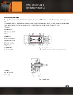
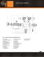
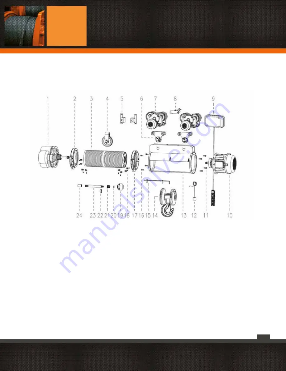
Fig. 3  Constructional Drawing for PWMD10T24M

1. Speed reducer
2. Right rotation rope guide
3. Drum device
4.  Balance wheel device
5. Switch connector
6. Beam-balanced device
7. Electric hoist
8. Soft cable introducer
9. Control box  
10. Lifting motor
11. Coupling screw

12. Heavy hammer limiter 
13. Drum cover
14. Hook device
15. Rod limiter
16. Coupling screw
17. Left rotation rope guide 
18. Tightened pad
19. Elastic coupling
20. Bearing shield 
21. Splined hub
22. Bearing

23. Intermediate shaft 
24. Solid coupling

STRUCTURAL FEATURES

Summary of Contents for PWMD Series

Page 1: ...1 PWMD and PWMDF SERIES User Manual and Security Warnings...

Page 2: ...t in the selection of the equipment the capacities and characteristics required by the clients that Prowinch provides is delivered free of charge and provided based on the information of use and requi...

Page 3: ...E RUNNING PRINCIPLE 11 Model CD1 MD1 Electric Hoist 15 Hoisting Mechanism 15 Traversing Mechanism 23 Electric Devices 26 INSTALLATION AND ADJUSTMENT 30 INSPECTION AND TEST 31 PRECAUTION AND TROUBLE SH...

Page 4: ...D AND PWMDF HOIST MODELS PWMD2T12M PWMD3T24M PWMD5T24M PWMDF3T24M PWMDF5T24M PWMD10T24M PWMD16T24M PWMD20T24M PWMD25T18M PWMD50T12M PWMD50T20M PWMDF10T24M PWMDF16T24M PWMDF20T24M PWMDF25T18M PWMDF50T1...

Page 5: ...rd party safety The inadequate operation of the equipment may cause injuries or harm the equipment Read and understand this manual carefully before installation and commissioning of the equipment Keep...

Page 6: ...hoes and eyes protection WARNING This symbol indicates a dangerous situation which if not avoid may cause minor or moderate wounds It is also used for indicating unsafe practices DANGER This symbol in...

Page 7: ...eep a safe distance Make sure that people are away from the hoist wire rope when operating the equipment It s suggested that the distance betce between personnel and the Hoist should be at least 1 5 t...

Page 8: ...r the load it may fall and cause death 8 Verify installation 6 Do not use the hoist under the rain Do not wet the engine or the switch 2 Check the electrical connections Vol tage may vary if not prope...

Page 9: ...ure to rain or extreme humidity It may cause rusting of the equipment If used near chemicals corrosive gas or explosives may cause an explosion Exposure to salt or acids may cause malfunctioning Expos...

Page 10: ...the site where the environmental temperature ranges 20 C 40 C but not suitable in hazadous areas of explosion and flame in the site full of acid gas or other corrosion gases and in the site with the r...

Page 11: ...vices 3 Electric Trolley 4 Traversing Reducer 5 Traversing Motor 6 Hook Device 7 Hoisting Motor 8 Power cut Space Limiter 9 Space Limit Lever 10 Rope Guide Device 11 Stop Block 12 Hoisting Reducer 13...

Page 12: ...Structure and Outline of Electric Hoist Model CD110t H 9m 40m apart from 16 1 15 in Fig lc are the same as those in Fig 1a 1b Fig 1d Structure and Outline of the Stationary Electric Hoist Model CDI MD...

Page 13: ...13 A1 is top mounting A2 is bottom mounting A3 is left mounting A4 is right mounting MAIN STRUCTURE RUNNING PRINCIPLE...

Page 14: ...Device Fig 1f Structure and Outline of Electric Hoist Model MD1 1t 5t H 12m 40m Fig 1g Structure Outline of Electric Hoist Model MD1 10t H 9m 40m apart from14 15 1 13 in Fig lg are the same as those...

Page 15: ...and rotating roughly or bent caused by trembling as it is very long A transmitting mechanism of 3 stage outside meshed bevel gears is used for he reducer See Fig 3 The gears and shafts are made of all...

Page 16: ...r of big motor turning together Understandable the speed of big motor is only 1 i generally approximate to 1 10 of the small motor Turned on the big motor the brake is unclamped and the big motor runs...

Page 17: ...17 MAIN STRUCTURE RUNNING PRINCIPLE...

Page 18: ...18 MAIN STRUCTURE RUNNING PRINCIPLE...

Page 19: ...19 MAIN STRUCTURE RUNNING PRINCIPLE...

Page 20: ...20 MAIN STRUCTURE RUNNING PRINCIPLE...

Page 21: ...21 MAIN STRUCTURE RUNNING PRINCIPLE...

Page 22: ...22 MAIN STRUCTURE RUNNING PRINCIPLE...

Page 23: ...the braking torque is comparative smaller and the braking process slow to avoid the load from vacillation when stopping the trolley 1 Reducer 2 Hollow Shaft 3 Reducer Input Shaft 4 Drum 5 Rigid Shaft...

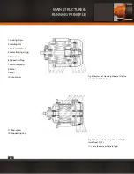
Page 24: ...ting Ring 7 Pressure Spring 8 Stator 9 Rotor 10 Front cover Fig 4 Structure of Hoisting Motor of Electric Hoist Model CDI0 5t 5t 11 Rear cover 12 Supporting Cap Fig 5 Structure of Hoisting Motor of El...

Page 25: ...25 Fig 6 The Double motor Group of Electric Hoist Model MDI 0 5t 5t Fig 7a The Double motor Group of Electric Hoist Model MDI 10t MAIN STRUCTURE RUNNING PRINCIPLE...

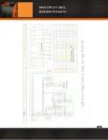
Page 26: ...the cable is connecting with terminal panel The electricity control and operation is at safety voltages normally is 36v The power cut space limiter is used to prevent accident which may be caused by t...

Page 27: ...on Start on the KO AC contactor acts in self security mode so as to pro vide power for other contactors When the power in accident shot cut the KO contactor losses electricity simultaneously the main...

Page 28: ...28 MAIN STRUCTURE RUNNING PRINCIPLE...

Page 29: ...29 MAIN STRUCTURE RUNNING PRINCIPLE...

Page 30: ...raking torque then tighten the screw 1 shortening the slide down distance Watch carefully the leap clearance of motor shaft when starting and stopping the motor repeatedly or press the shaft end of mo...

Page 31: ...order 4 5 If it is loose or in disorder the wire rope should be rearranged in right order and tightened 4 6The position of the stop blocks fixed on the lever of the space limiter should be checked an...

Page 32: ...1 8 2 Pay attention to the fixing condition at the ends of the wire rope in the periodical inspection 5 1 8 3 Some measures should be taken to prevent it from twist together crisscross be curved to fo...

Page 33: ...33 PRECAUTION AND TROUBLE SHOOTING...

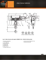
Page 34: ...hield 7 Splined hub 8 Beam balanced device 9 Two wheel trolley device 10 Electric trolley 11 Soft cable introducer 12 Switch connector 13 Control box 14 Lifting motor 15 Coupling screw 16 Rod limiter...

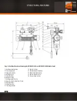
Page 35: ...anced device 7 Electric hoist 8 Soft cable introducer 9 Control box 10 Lifting motor 11 Coupling screw 12 Heavy hammer limiter 13 Drum cover 14 Hook device 15 Rod limiter 16 Coupling screw 17 Left rot...

Page 36: ...he first shaft assembly 9 The second shaft assembly 10 The third shaft assembly 11 Sealing ring 12 Gear teeth 13 Gear box body 14 Bearing 15 Bearing cover 16 Round pin 17 Washer 18 Oil plug 19 Couplin...

Page 37: ...6 Front end cap 7 Hole ring 8 Bearing 9 Round wire snap ring 10 Rotor assembly 11 Surface bearing 12 Bearing 13 Shield cap 14 Rivet 15 Nameplate 16 Stator assembly 17 Back end cover 18 Fan brake wheel...

Page 38: ...ring 13 Bearing 14 Double speed body 15 Bearing 16 Double speed big gear wheel 17 Fan brake wheel 18 Lock nut 19 Screw 20 Spring washer 21 Double speed cover 22 Screw 23 Spring washer 24 Ring shield 2...

Page 39: ...g motor 2 Coupling screw 3 Bearing cap 4 Travelling speed reducer body 5 Sealing gasket 6 Ring shield 7 Snap ring 8 Big driving gear 9 Space ring 10 Bearing 11 Gear shaft 12 Flat key 13 Ring shield 14...

Page 40: ...lectric trolley 1 Wall board 2 Wheel axle 3 Space ring 4 Ring shield 5 Shield cap 6 Bearing 7 Driving wheel 8 Ring shield 9 Shield cap 10 Hole ring 11 Trolley bolt 12 Washer of trolley bolt 13 Trolley...

Page 41: ...ectric hoist 1 Hoisting speed reducer 2 Driven wheel system 3 Drum equipment 4 Hook assembly 5 Hoisting motor 6 Electric wheel system 7 Heavy hammer limiter 8 Traveling reducer 9 Wheel system shim 10...

Page 42: ...3T24M PWMDF5T24M Fixed hoist 1 Hoisting speed reducer 2 Drum equipment 3 Rope guide device 4 Control button 5 Hoisting motor 6 Hook assembly 7 Hoisting weight limiter 8 Heavy hammer limiter for 5T use...

Page 43: ...3T24M PWMDF5T24M Fixed hoist 1 Hoisting speed reducer 2 Drum equipment 3 Rope guide device 4 Control button 5 Hoisting motor 6 Hook assembly 7 Hoisting weight limiter 8 Heavy hammer limiter for 5T use...

Page 44: ...MDF16T24M and PWMDF20T24M Fixed hoist 1 Hoisting speed reducer 2 Drum equipment 3 Hoisting weight limiter 4 Heavy hammer limiter 5 Rope guide device 6 Hoisting motor 7 Control button 8 Hook assembly 9...

Page 45: ...cer 2 Drum equipment 3 Rope guide device 4 Hoisting motor 5 Control button 6 Hook assembly 7 Hoisting weight limiter 8 Heavy hammer limiter for 5T use 9 Traveling motor 10 Adjustingshim 11 Traveling r...

Page 46: ...ope guide device 4 Hoisting motor 5 Control button 6 Hook assembly 7 Hoisting weight limiter 8 Heavy hammer limiter for 5T use 9 Traveling motor 10 Adjusting shim 11 Traveling reducer 12 Electric syst...

Page 47: ...for hoisting weight limiter 4 Heavy hammer limiter 5 Rope guide device 6 Hoisting motor 7 Control button 8 Hook assembly 9 Heavy hammer limiter 10 Traveling motor 11 Adjusting shim 12 Traveling reduc...

Page 48: ...Drum equipment 3 Hoisting weight limiter 4 Heavy hammer limiter 5 Rope guide device 6 Hoistingmotor 7 Control button 8 Hook assembly 9 Beam balanced device 10 Traveling motor 11 Adjusting shim 12 Tra...

Page 49: ...5T24M Fixed Hoist 1 Hoisting speed reducer 2 Drum equipment 3 Rope guide device 4 Hoisting two speed motor set 5 Control button 6 Hook assembly 7 Hoisting weight limiter 8 Heavy hammer meter limiter f...

Page 50: ...st 1 Hoisting speed reducer 2 Drum equipment 3 Balance weight for hoisting weight limiter 4 Hoisting weight limiter 5 Rope guide device 6 Hoisting two speed motor set 7 Control button 8 Hook assembly...

Page 51: ...nd PWMDF20T24M Fixed Hoist 1 Hoisting speed reducer 2 Drum equipment 3 Hoisting weight limiter 4 Heavy hammer limiter 5 Rope guide device 6 Hoisting two speed motor set 7 Control button 8 Hook assembl...

Page 52: ...uipment 3 Rope guide device 4 Hoisting two speed motor set 5 Control button 6 Hook assembly 7 Hoisting weight limiter 8 Heavy hammer limiter for 5T use 9 Traveling motor 10 Adjusting shim 11 Traveling...

Page 53: ...de device 4 Hoisting two speed motor set 5 Control button 6 Hook assembly 7 Hoisting weight limiter 8 Heavy hammer limiter for 5T use 9 Traveling motor 10 Adjusting shim 11 Traveling reducer 12 Electr...

Page 54: ...r heavy hammer limiter 4 Heavy hammer limiter 5 Rope guide device 6 Hoisting two speed motor set 7 Control button 8 Hook assembly 9 Heavy hammer limiter 10 Traveling motor 11 Adjusting shim 12 Traveli...

Page 55: ...quipment 3 Heavy hammer limiter 4 Heavy hammer limiter 5 Rope guide device 6 Hoisting two speed motor set 7 Control button 8 Hook assembly 9 Beam balanced device 10 Traveling motor 11 Adjusting shim 1...

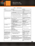
Page 56: ...stuck under the effect of temperature or humidity and the motor blockage will occur if power on at this time Troubleshooting remove the fan cover of motor insert the screwdriver or other crowbar to t...

Page 57: ...amount is large after using a stage the adjustment method is to loose screw 1 rotate counterclockwise the adjustable locknut 2 about 1 2 scales then tighten the screw 1 PWMD 10T 16T and 20T brake adju...

Page 58: ...axial movement of fan blade brake wheel using lever 3 the normal movement is around 2 mm 2 If the brake glide amount is large after using a stage the adjustment method is to loose screw 1 rotate count...

Page 59: ...59 PWMD 10T 16T and 20T brake adjustments ANNEX 2 Lubrication Schematic Diagram PWMD single speed electric hoist PWMD double speed electric hoist ANNEX...

Page 60: ...60 ANNEX 3 Electric diagram for PWMD Electric Hoist Connecting box fixed on M1 Note M2 is not used in fixed electric hoist ANNEX...

Page 61: ...61 Control Principle Diagram for PWMD 0 25T Electric Hoist Note 1 Temperature controlled switch Rt is optional to assembly by user when ordering 2 M2 are all not adopted in fixed electric hoists ANNEX...

Page 62: ...s not adopted in fixed electric hoist 2 Temperature controlled switch R1 is selected to assembly by user when ordering 3 Underlined manufacture unit in diagram has been wired users only need to connec...

Page 63: ...ot adopted in fixed type electric hoists Electricity Schematic Diagram for PWMD3T 20T Electric Hoist Note 1 M3 in figure is only used for 10t and 16tand 20t traveling electric hoist M2 and M3 are not...

Page 64: ...for users Note 1 M3 is not adopted in fixed type electric hoist 2 Temperature controlled switch R1 is selected to assembly by user when ordering 3 Underlined manufacture unit in diagram has beenwired...

Page 65: ...hammer limitXS is only used in 5 20t Note 1 M4 in figure is only used for 10T 16T and 20T traveling electric hoists and M3 and M4 is not adopted in fixed type electric hoists 2 Temperature controlled...

Page 66: ...66 b PWMD3T24M TECHNICAL SPECIFICATIONS...

Page 67: ...67 c PWMD5T24M TECHNICAL SPECIFICATIONS...

Page 68: ...68 d PWMD10T24M TECHNICAL SPECIFICATIONS...

Page 69: ...69 e PWMD16T24M TECHNICAL SPECIFICATIONS...

Page 70: ...70 f PWMD20T24M TECHNICAL SPECIFICATIONS...

Page 71: ...71 g PWMD25T18M TECHNICAL SPECIFICATIONS...

Page 72: ...72 h PWMD50T12M TECHNICAL SPECIFICATIONS...

Page 73: ...73 i PWMD50T20M TECHNICAL SPECIFICATIONS...

Page 74: ...74 j PWMDF3T24M TECHNICAL SPECIFICATIONS...

Page 75: ...75 k PWMDF5T24M TECHNICAL SPECIFICATIONS...

Page 76: ...76 l PWMDF10T24M TECHNICAL SPECIFICATIONS...

Page 77: ...77 m PWMDF16T24M TECHNICAL SPECIFICATIONS...

Page 78: ...78 n PWMDF20T24M TECHNICAL SPECIFICATIONS...

Page 79: ...79 o PWMDF25T18M TECHNICAL SPECIFICATIONS...

Page 80: ...80 p PWMDF32T18M TECHNICAL SPECIFICATIONS...

Page 81: ...81 q PWMDF50T12M TECHNICAL SPECIFICATIONS...

Page 82: ...82 r PWMDF50T20M TECHNICAL SPECIFICATIONS...

Page 83: ...ely if any type of intervention is done to the equipment 9 Every Prowinch equipment has a warranty seal In case it is broken warranty will expire immediately 10 Warrantywillendifequipmentinnotinstalle...

Page 84: ...84...

Reviews: