15
Installation
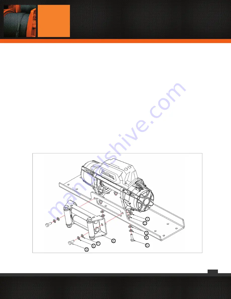
1) Install a suitable mounting bumper, or mounting plate in
the required position. The winch must be mounted with the
direction of pull perpendicular to the mounting bolt fixings.
The steel plate should be at least 6mm thick.
2) Attach fairlead (4-Way Roller type for wire rope or
Aluminium Hawse for Synthetic Rope) to mounting plate using
two nuts (9) and bolts (1) with flat (7) and spring washers (8).
3) Insert
the four square nuts (2) into the pockets at the base
of the winch frame.
4) Thread
the four high tensile bolts (5) with flat (3) and spring
(4) washers up through the mounting plate and into the square
nuts in the winch. Tighten the mounting bolts to a torque
setting of 60 Nm.
5) The supplied bolts are the correct length for installation
on a 6-7mm plate. Other thicknesses may require bolts of a
different length. Use at least 8.8 grade high tensile bolts, the
thread length should be sufficiently long to fully engage the
square nut but must not bottom out on the top of the pocket
in the winch frame.
6) Feed the end of the wire rope through the roller fairlead (6)
and attach the clevis hook or with a synthetic rope with fixed
hook, feed the drum end of the synthetic rope through the
hawse from the front and attach to the drum using the allen
head cap screw finger tight only, ready for spooling onto the
drum.
4.2 MOUNTING THE WINCH
(please refer to Fig. 3).
Fig. 3
Summary of Contents for PWTR Series
Page 1: ...1 User s Manual and Safety Warnings PWTR SERIES...
Page 26: ...26 Technical Parameters...
Page 27: ...27 Technical Parameters...
Page 28: ...28 9 1 PARTS DIAGRAM PWTR9500 PWTR13000 Parts Diagram...
Page 30: ...30 9 3 PARTS DIAGRAM PWTR15000 PWTR17000 Parts Diagram...
Page 31: ...31 Parts List...
Page 34: ...34...
Page 35: ...35...
Page 36: ...36...


