xviii
Proxess C-Series Service Manual
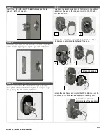
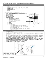
STEP 5
STEP 7
Slide the lock chassis through the chassis hole in the door,
ensuring that the chassis engages the latch.
Disconnect the handle switch connector from the interior
board.* Place the outside rose liner on the interior back plate
and screw in. Ensure that both the handle switch connector and
FFC connector sit in the side channels around the rose liner
while the motor and latch connectors are fed through the rose
liner.
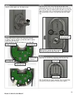
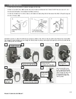
* TO CONNECT AND DISCONNECT THE 4 AND 10-
PIN CONNECTORS
To connect the pin connectors (FFC and handle switch), begin
by pushing up the black cowl.
Then insert the cable with the wires facing away from you and
push until you hear a click.
Push the black cowl back down to secure the connector.
To disconnect the connectors, push up on the black cowl and
pull out the cable.
STEP 6
Place the back plate on the interior of the door with the upper
and lower screws near the chassis. Wire the cable and wires as
shown:
Motor and latch
connectors
FFC connector
Handle switch
connector
1
2
3
Summary of Contents for PX10100001
Page 1: ...C Series Service manual...

