Installation and Initialization
QB.11-R Installation and Management
Installation Procedure
25
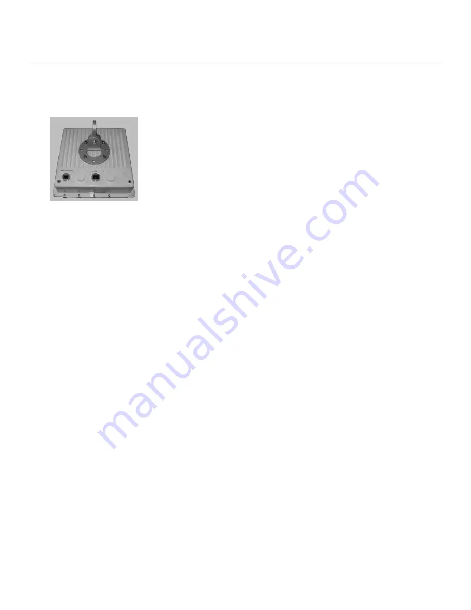
The following figure shows the full assembly attached to the unit:
Note that this figure is for illustration only. Units with integrated antennas must always be mounted in diagonal position
to achieve vertical or horizontal polarization as indicated by the arrow on the back of the unit. Also, on units with direct-
connected omni antennas, the enclosure must be mounted with the lower side in the horizontal position.
Step 7: Perform Confidence Test (Optional)
This step allows you to verify the equipment’s operation and test a wireless link between the BSU and SU prior to the
actual installation. If you wish to proceed without performing a confidence test, continue to
To perform a confidence test:
1. Place the units on a tabletop or shipping box, positioning them at least 10 feet from each other. If the units are too
close together, the radio signal from the antennas may be too strong to get good reception, resulting in a bad quality
due to distortion in the receiver. Do not aim the antennas at each other, as this may cause too high a signal level.
2. Plug one end of the CAT5 cable into the RJ45 jack of the BSU.
3. Connect the free end of the CAT5 cable to the “Data and Power Out” port on the power injector.
4. To connect the BSU through a hub or a switch to a PC, connect a straight-through Ethernet cable between the
network interface card in the PC and the hub, and between the hub and the RJ45 “Data In” port on the PoE adapter.
To connect the BSU directly to a PC, connect a cross-over Ethernet cable between the network interface card in the
PC and the RJ45 “Data In” port on the power injector.
5. Repeat steps 2 through 4 for the SU.
6. Connect the power injector cord for each unit into an AC outlet. When the units are powered on, they perform startup
diagnostics. When startup is complete, the wireless LED should briefly blink green and turn solid green when the
wireless link between the two units is established.
7. Verify that the SNR (Signal to Noise Ratio) is no more than 50 dB to guarantee a good reception. The SNR is
displayed in the Link Test and Per Station monitoring Web interface pages, and also displayed on the serial port
through the CLI when the serial dongle is plugged into the unit. If the SNR is greater than 50 dB, reposition the units.
8. Verify that the network connection is working correctly (by accessing the Web or e-mail).
9. When all tests have passed successfully, the wireless point-to-point bridge is ready to be installed.
Proxim recommends that the BSU be installed at the location from where you expect the wireless network to be extended
in the future.


