
- 7 -
Technical data
Grinding speed:
250 - 750 m/min
Abrasive disk:
Ø 250 mm
Max. grinding height:
135 mm
Table adjustment:
15° upwards, 45° downwards
Noise level:
72 dB(A)
Vibration:
2.5 m/s
2
Working table:
275 x 105 mm
Overall size:
330 x 280 x 230 mm
Motor:
Voltage:
115 V / 60 Hz
Power consumption:
200 Watt
Unit Assembly
Warning !
To avoid injury from unexpected starting or electrical
shock, do not plug the power cord into a power source
receptacle during unpacking and assembly. This cord must
remain unplugged whenever you are working on the disk
sander.
Warning!
If any part is missing or damaged, do not plug the disk
sander in until the missing or damaged part is replaced,
and assembly is complete. To avoid electrical shock, use
only identical replacement parts when servicing double
insulated tools.
Warning!
Do not attempt to modify this tool or create accessories
not recommended for use with this tool. Any such
alternation or modification is misuse and could result in
hazardous condition leading to possible serious injury.
1. Remove the disk sander from the packaging and check
if any parts are missing.
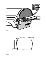
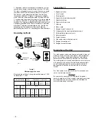
2. Fasten unit using fastening bolts onto a stable
workbench or working surface, as per fig. 2.
Adjust Angular Indicator
Warning!
For your own safety, do not plug the tool into the power
source receptacle or insert the switch key, until the parts
are correctly installed and adjustments have been made.
1. Slightly release clamping bolt
10 (fig.1) and align the
working table 3 to precisely 90° (using a square) (fig. 6).
Retighten the clamping bolt.
2. Check and if necessary correct the zero setting of the
indicator
12 (fig. 1), after releasing the clamping bolts.
Note:
Perform a grinding test before performing precision work.
3. Grind a piece of wood and check the angle, if necessary
readjust the working table
3 (fig. 1) and the indicator 12.
Replacing the Abrasive Disk
Warning!
To avoid injury from accidental start, make sure the switch
is in the OFF position and the plug is not connected to the
power source receptacle before changing any parts or
discs.
Remove the abrasive disk
Caution!
Disconnect the mains plug from the power socket.
Warning!
For your own safety, use only abrasive discs sized and
recommended for this disk grinder. Follow the instructions
that accompany the disk grinder.
Note:
The protective cover must be removed when changing the
abrasive disk.
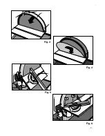
1. Detach the liquid cooling system pipes from the spigots
3 (fig. 3) on the protective cover if present. Release the
fastening bolts 1 and remove the protective cover 2.
2. Detach the abrasive disk from the grinding plate using a
blunt knife or a chisel and remove the abrasive disk
halfway.
The disk can be easily removed from the plate by heating
the adhesive with a hot-air blower.
Important!
Do not damage the grinding plate!
3. Turn the grinding plate approx. 180° and remove the rest
of the disk.
Attaching New Sheet of Abrasive Material
Note:
Thoroughly clean the grinding plate before applying the
new abrasive disk.
Warning!
Use only accessories recommended for this disk sander.
Follow the instructions that accompany accessories. Use
of improper accessories may cause hazards.
1. Pull off half of the protective foil for the new abrasive
disk.
2. Insert the abrasive disk halves with the protective foil
between the working table and the grinding plate (fig. 4).


