

- 8 -
Note:
When applying the abrasive disk on the grinding plate,
start from the centre and work outwards.
3. Apply the top half of the abrasive disk on the grinding
plate precisely in the correct position.
4. Rotate the grinding plate approx. 180°, remove the
second half or the protective foil and use the same
procedure to apply the disk.
5. Reattach the protective cover.
Working with the Disk sander
Important!
Safe and precision working practice can only be ensured
with the unit properly secured!
Do not leave the unit switched on if unsupervised.
1. Switch on the disk sander.
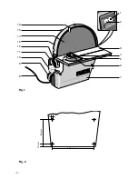
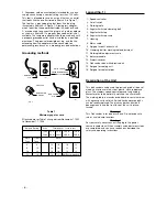
2. Adjust the rotational speed of the disk sander using the
speed controller
1 (fig. 1).
3. Place the work piece on the working table, guide it
gently and carefully.
4. Always exert pressure on the working table rather than
against the abrasive disk.
Note:
Please note the following items in order to ensure good
grinding results:
1. Do not overload the unit (if the fuse blows, only use an
original fuse (1.25 T) as a replacement)!
2. The disk sander is primarily designed for grinding
precise angles. The more accurately the work piece is
pre-cut, the quicker and easier it will be to produce
precise angles and the less abrasive disks will be
required to perform the task.
3. Please note the dissimilar grinding speeds for the
abrasive disk (fig. 6):
inner diameter = low speed
outer diameter= high speed
4. The abrasive disk turns in an anti-clockwise direction.
For this reason, only grind on the left half of the working
table.
Important!
Only use abrasive disks which are in a flawless
condition. Replace worn abrasive disks promptly.
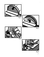
Grinding a Mitre with the Working Table Inclined
1. Release the clamping bolt
2 (fig. 5) and set the working
table to the desired angle (e.g., 45°).
2. Tighten clamping bolt 2.
3. Set angular limit stop
1 (fig. 5) to position "0"
With horizontally set working table
1. Release the clamping bolt
2 (fig. 6) and set the working
table horizontally (indicator at "0").
2. Tighten clamping bolt 2.
3. Set the angular limit stop
1 (fig. 6) to the desired angle
(e.g., 45°).
Liquid Cooling System
We recommend that the liquid cooling system is attached
when grinding iron, steel and non-ferrous metals, as well
as stone, tiles, ceramics (not included in scope of supply,
available as an accessory).
The heat arising from grinding operations is dissipated by
supplying coolant, thus improving the resulting surface
quality.
Dust Extract Connection
In order to permit a dust-free working environment, the
disk sander is equipped with a vacuum cleaner connection
for dust extraction.
Important!
When using both a vacuum cleaner (as a dust extract unit)
and the liquid cooling unit, ensure that the vacuum cleaner
is suitable for aqua cleaning as well.
1. Connect the vacuum cleaner hose to the connection
spigot
9 (fig. 1).
2. Switch on the vacuum cleaner.
3. Switch on the disk sander, grind the work piece.


