background image

Seite 12 

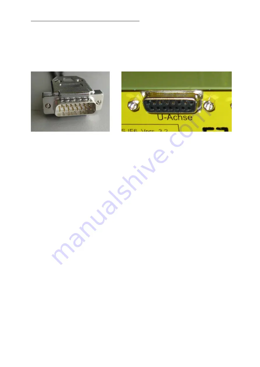
Fig.4 

Fig. 5 

Connecting the dividing head to the control 
 

The plug of the dividing head must be inserted into the provided socket at the rear of the 
control. Figures 4 and 5 show the plug (top) and the socket labelled “u-Axis”. 
 
For  safety  reasons,  please  screw  the  slotted  screws  of  the  plug  into  the  designated 
threads at the control and tighten carefully.  This prevents the  plug from falling out on its 
own or from being pulled out accidentally.


Summary of Contents for UT 400 CNC

Page 1: ...Seite 1 Betriebsanleitung Manual Teilapparat Dividing head UT 400 CNC Art 24423 Ver 02 12 10...

Page 2: ...nnend 24408 4 Backen Drehfutter zentrisch spannend 24410 4 Backen Drehfutter mit einzeln verstellbaren Backen N here Informationen ber unser gesamtes umfangreiches Zubeh rprogramm f r Ihren UT 400 CNC...

Page 3: ...das Fenster f r die Editierung der Maschinenparameter ausw hlen Dort die erforderlichen Karten anw hlen und falls notwendig die mit Pfeilmarkierungen versehenen Einstellungen vornehmen siehe Fig 2 und...

Page 4: ...ng eingesteckt werden Die Abbildungen Fig 4 und 5 zeigen den Stecker oben und die mit U Achse gekennzeichnete Buchse Bitte schrauben Sie zur Sicherheit die Schlitzschrauben am Stecker in die daf r vor...

Page 5: ...heit Zun chst m ssen die 3 mitgelieferten Vierkantmuttern wie auf dem Foto gezeigt in die Nuten am Kreuztisch geschoben werden mit diesen werden drei Befestigungsschrauben verschraubt Diese werden von...

Page 6: ...Drehen der Futteraufnahme 1 Software starten 2 Im Men Maschine anklicken 3 Fr smaschine anklicken 4 Das Fenster f r die Handsteuerung geht auf Mittels Dr cken der und Tasten auf der Computertastatur k...

Page 7: ...nden Diese sind f r die Verwendung in Kombination mit dem UT 400 CNC ausgelegt Schwenken der Motor Getriebeeinheit Falls es die Bearbeitungsaufgabe die Aufspannung auf dem Kreuztisch bzw die Werkst ck...

Page 8: ...L sen Sie den Gewindestift unter Zuhilfenahme eines Innensechskant Schl ssels 3 mm etwas wie in Fig 14 gezeigt 2 Nun k nnen Sie die Motor Getriebeeinheit etwas nach oben d h in Richtung der Spannmitt...

Page 9: ...zeichnung Teilapparat UT 400 CNC Artikel Nr 24423 Wir erkl ren in alleiniger Verantwortung dass dieses Produkt mit den folgenden Richtlinien bereinstimmt EU EMV Richtlinie 2004 108 EG EU Maschinenrich...

Page 10: ...4407 3 jaw chuck centrically clamped 24408 4 jaw lathe chuck centrically clamped 24410 4 jaw lathe chuck with individually adjustable jaws More information on our entire comprehensive accessories prog...

Page 11: ...application click on the menu item Parameter and then select the window for editing the machine parameters Next select the required tabs and make the settings marked by the arrows see Fig 2 and 3 Ligh...

Page 12: ...ovided socket at the rear of the control Figures 4 and 5 show the plug top and the socket labelled u Axis For safety reasons please screw the slotted screws of the plug into the designated threads at...

Page 13: ...in the body of the unit First the 3 supplied square nuts as shown in the photo must be pushed into the grooves of the compound table and screwed together with three fastening screws These are inserte...

Page 14: ...controlled turning of feed receiver 1 Start the software 2 In the menu click Machine 3 Click Milling machine 4 The window for manual control appears By pressing the and keys on the computer keyboard...

Page 15: ...PROXXON lathe chuck or the PROXXON face plate These are designed for use in combination with the UT 400 CNC Swivelling the motor gear unit If required by the processing task the clamping on the compo...

Page 16: ...1 Release the threaded pin by using a 3 mm Allen wrench similar to that shown in Fig 14 2 Now you can swivel the motor gear unit up a bit i e in the direction of the clamping device holder until you...

Page 17: ...ker Product designation Dividing head UT 400 CNC Article No 24423 In sole responsibility we declare that this product conforms to the following directives EU EMC Directive 2004 108 EC EU Machinery Dir...

Page 18: ...Aist Wir reagieren prompt und zuverl ssig ber diese Adresse k nnen Sie auch alle erforderlichen Ersatzteile bestellen Wichtig Eine kurze Fehlerbeschreibung hilft uns noch schneller zu reagieren Bei R...

Reviews: