Seite 16
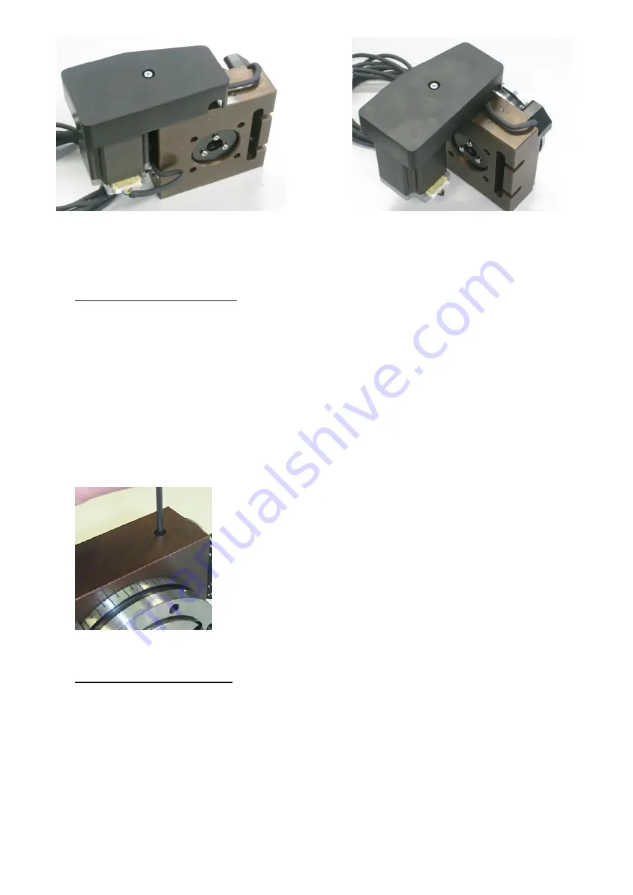
Fig. 12
Fig. 13
Fig. 11
Setting the gear allowance
After a certain operating period, wear will inevitably cause play in the worm gear of the
dividing head.
This process cannot be stopped, but is not a defect. To re-establish the accustomed
precision of the dividing head, this play can be minimized quite simply through
adjustments.
To do so, swivel the motor-gear unit as necessary to guarantee accessibility to the locking
screw for the gear worm, see section “Swivelling the motor-gear unit”. The necessary
steps are explained there in detail.
1. Release the threaded pin by using a 3 mm Allen wrench,
similar to that shown in Fig. 14.
2. Now, you can swivel the motor-gear unit up a bit (i.e. in
the direction of the clamping device holder) until you notice
some resistance.
3. During this procedure, continually activate the manual
control of the dividing head and make sure that the rotation
movements occur properly. If that is not so, then release some
pressure from the motor-gear unit until the movement occurs
normally once more.
4. Retighten the threaded pin as per Fig. 14.
Clamping the work pieces
The feed receiver is provided with a centring collar with a 70 mm fit.
This is suitable for fastening the various PROXXON 3- or 4-jaw chucks and the face
plates (all from the PD 400 lathe system).
Fig. 10


