Horizontal shaft alignment
65
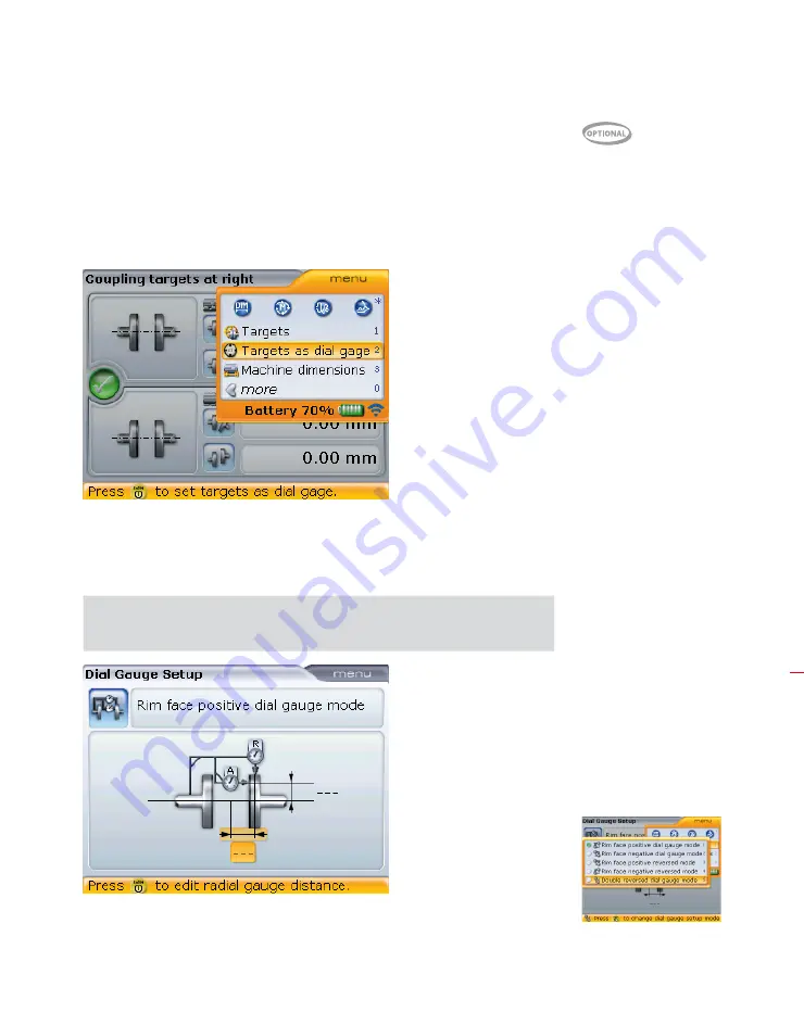
5 .7 .7 Entering coupling target values as dial indicator readings
Coupling target values given in terms of dial indicator readings can be entered into
OPTALIGN smart computer for conversion to gap and offset. If the function coupling
targets is enabled, the converted values are automatically taken into account when
determining the alignment condition. To enter dial indicator measurements proceed
by pressing
q
while in the “Coupling targets” screen.
When the context menu appears, use
f
/
g
and highlight ‘Targets as dial
gauge’ and the press
e
to confirm selection. This prompts the “Dial gauge set-
up”screen.
Note that a hint to set up the dial gauge configuration will appear followed by
the “Dial gauge set-up” screen.
Use the navigation keys to exit the header and cycle
through the required dimensions. Enter the required
dimensions.
The “Coupling targets”
screen is accessed as
described in section 5.7.4.
H
Note
The dial gauge configura-
tion is set at the header.
Use the navigation keys
to highlight the header
then cycle through the
various configurations by
pressing
e
with header
highlighted. Alternatively,
use the “Dial gauge set-up”
screen context menu to
select desired dial gauge
configuration.
Summary of Contents for OPTALIGN smart RS5 BT
Page 10: ...OPTALIGN smart RS5 BT handbook 10 Page intentionally left blank ...
Page 16: ...OPTALIGN smart RS5 BT handbook 16 This page intentionally left blank ...
Page 28: ...OPTALIGN smart RS5 BT handbook 28 Page intentionally left blank ...
Page 38: ...OPTALIGN smart RS5 BT handbook 38 This page intentionally left blank ...
Page 112: ...OPTALIGN smart RS5 BT handbook 112 This page intentionally left blank ...
Page 174: ...OPTALIGN smart RS5 BT handbook 174 This page intentionally left blank ...
Page 194: ...OPTALIGN smart RS5 BT handbook 194 This page intentionally left blank ...


