6-7
ROTALIGN 01.2000
Machine preparation
Certain preparations should be made before beginning any alignment
to ensure efficient measurement and successful results.
Ensure that the machine cannot accidently be started before
commencing work.
Solid, flat foundation
A solid, rigid foundation is required to obtain correct, lasting shaft
alignment that allows long-term uninterrupted machine service.
Machine mobility
Shaft alignment in theory and in practice
If the machine to be moved stands directly on the foundations, it
cannot be lowered for alignment correction. Therefore, it is generally
advisable to start with about 2 mm (80 mils) of shims beneath the
feet of both machines.
Precut shims such as single-thickness PERMABLOC or laminated
LAMIBLOC shims, available individually or as complete assortments
in carrying cases, should be on hand before beginning alignment (see
page 6-9). Horizontal alignment can be made easier and more precise
if hydraulic or screw-type positioning aids are available. The "ham-
mer method" is not only inexact, but it can also damage the machine
housing and bearings (by chatter marking).
Rigid couplings
Rigid couplings, typically found on turbines, must be loosened before
measurement so that they do not distort the alignment condition.
How this is done depends on the type of machine:
Steam turbines with single bearing shafts: Remove the coupling
bolts, split the coupling faces 2-3 mm (1/8") and insert a couple of
undersize dummy bolts.
Steam turbines with two bearing shafts: The coupling faces normally
locate together; the coupling must, therefore, be split sufficiently in
order to dislocate them. Alternatively, there may be a spacer
component which can be dropped out and the two halves linked with
a bar.
Gas turbines: These are usually fitted with a spacer shaft to
accommodate large thermal growths. Either a) remove the spacer
and use the Pass mode (page 4-36) or b) loosen the coupling as above
and use the Multipoint mode (page 4-36).
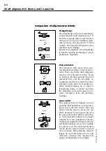
Tip:
Adjustment screws can easily be
made be tack welding a bolt to the
foundation and inserting a screw
vertical
2 mm
horizontal
WARNING!
Summary of Contents for ROTALIGN ALI 3.500
Page 13: ...1 10 ROTALIGN 01 2000 This page intentionally left blank ...
Page 103: ...4 66 ROTALIGN 01 2000 This page intentionally left blank ...
Page 121: ...5 18 ROTALIGN 01 2000 This page intentionally left blank ...
Page 143: ...6 22 ROTALIGN 01 2000 This page has intentionally been left blank ...
Page 158: ...6 37 ROTALIGN 01 2000 This page intentionally left blank ...


