4-43
ROTALIGN 01.2000
Horizontal machine alignment - options during measurement
Options during measurement
In addition to the aforementioned functions available in the measure-
ment modes, several additional features are also provided. Described
on the following pages are the XY View and the functions available in
the screen and the TABLE option.
XY VIEW
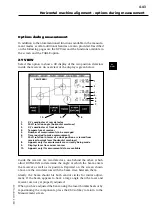
Select this option to show a 3D display of the two position detectors
inside the receiver. An overview of the display is given below.
XY
VIEW
1.
X,Y coordinates at rear detector
2.
Shaft rotation angle (horizontal machines)
3.
X,Y coordinates at front detector
4.
Temperature at receiver
5.
Number of measurements to be averaged
6.
Time required to make measurements
7.
Shaft rotation in terms of a clock position as viewed from
receiver towards laser (horizontal machines)
8.
Appears only if measurements are currently being made
9.
Displays laser trace across sensors
10.
Appears only if measurement data are available
Inside the receiver are two detectors, one behind the other, which
allow ROTALIGN to determine the angle at which the beam enters
the receiver as well as its position. Depicted on the screen shown
above are the two detectors with the beam trace between them.
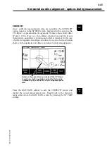
Ideally, the beam should hit both central circles for initial adjust-
ment. If the beam appears to have a large angle then the laser and
receiver are not yet properly adjusted.
When you have adjusted the beam using the laser thumbwheels or by
repositioning the components, press the ESC softkey to return to the
Measurement screen.
5.
6.
1.
2.
3.
4.
7.
CENTERED!
10.
8.
9.
Summary of Contents for ROTALIGN ALI 3.500
Page 13: ...1 10 ROTALIGN 01 2000 This page intentionally left blank ...
Page 103: ...4 66 ROTALIGN 01 2000 This page intentionally left blank ...
Page 121: ...5 18 ROTALIGN 01 2000 This page intentionally left blank ...
Page 143: ...6 22 ROTALIGN 01 2000 This page has intentionally been left blank ...
Page 158: ...6 37 ROTALIGN 01 2000 This page intentionally left blank ...


