ROTALIGN Ultra iS Shaft handbook
106
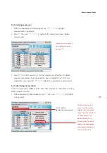
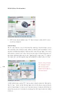
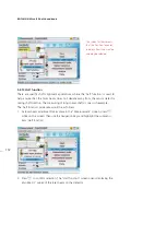
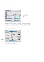
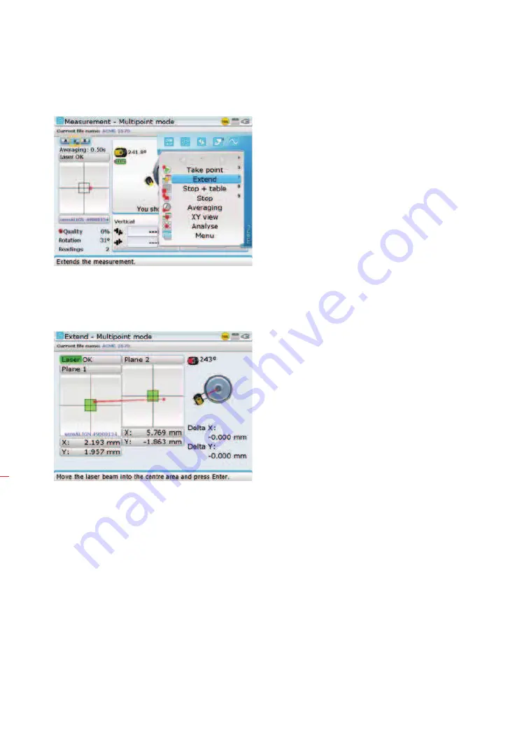
2. Use
f
/
g
to highlight ‘Extend’, then press
e
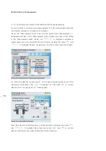
. The program holds up
measurement and switches to ‘XY View’ in the “Extend” screen. The current
beam position is automatically taken as the starting point for range extension.
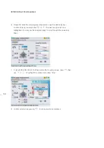
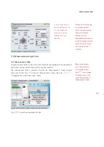
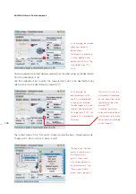
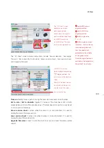
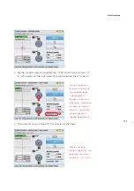
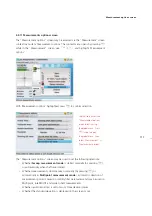
3. Readjust the beam into the target squares using the two yellow sensALIGN laser
horizontal and vertical position thumbwheels then press
e
or
ß
.
The adjusted beam position is taken as the end point of displacement.
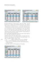
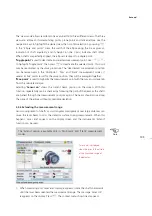
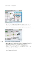
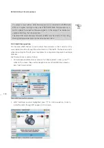
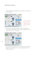
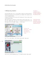
4. Continue measurement as before, rotating the shafts and pressing
e
to take
measurement at the desired positions.
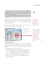
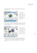
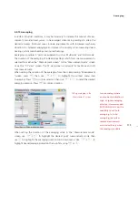
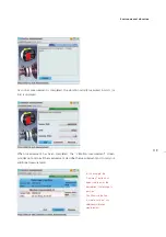
ROTALIGN Ultra iS Shaft program includes the displacement of beam readjust-
ment in the alignment calculations.
Summary of Contents for ROTALIGN Ultra iS
Page 1: ...ROTALIGN Ultra iS Operating handbook Shaft alignment...
Page 11: ...ROTALIGN Ultra iS Shaft handbook 10 This page intentionally left blank...
Page 56: ...55 Horizontal shaft alignment 1 2 4 5 6...
Page 123: ...ROTALIGN Ultra iS Shaft handbook 122 Page intentionally left blank...
Page 141: ...ROTALIGN Ultra iS Shaft handbook 140 This page intentionally left blank...
Page 177: ...ROTALIGN Ultra iS Shaft handbook 176 Page intentionally left blank...
Page 207: ...ROTALIGN Ultra iS Shaft handbook 206 Page intentionally left blank...
Page 213: ...ROTALIGN Ultra iS Shaft handbook 212 Declaration of conformity...

