ROTALIGN Ultra iS Shaft handbook
108
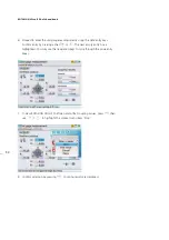
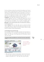
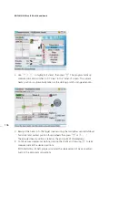
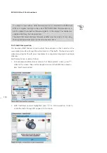
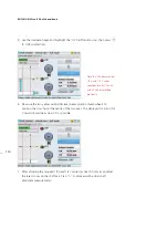
4. With the laser beam centered, press
e
then continue to rotate shafts to carry
on with measurement.
5.2.8 XY View
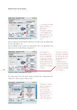
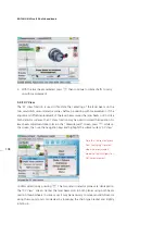
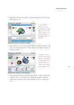
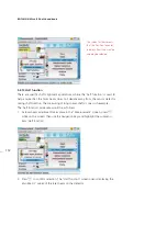
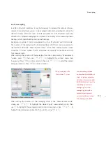
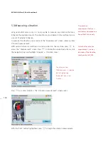
The XY View function is used to facilitate the centering of the laser beam on the
two sensALIGN sensor detector planes before proceeding with measurement. If the
angular and offset displacement of the laser beam causes the laser beam not to strike
both detector surfaces, the XY View function may be used to correct the deviation. As
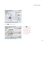
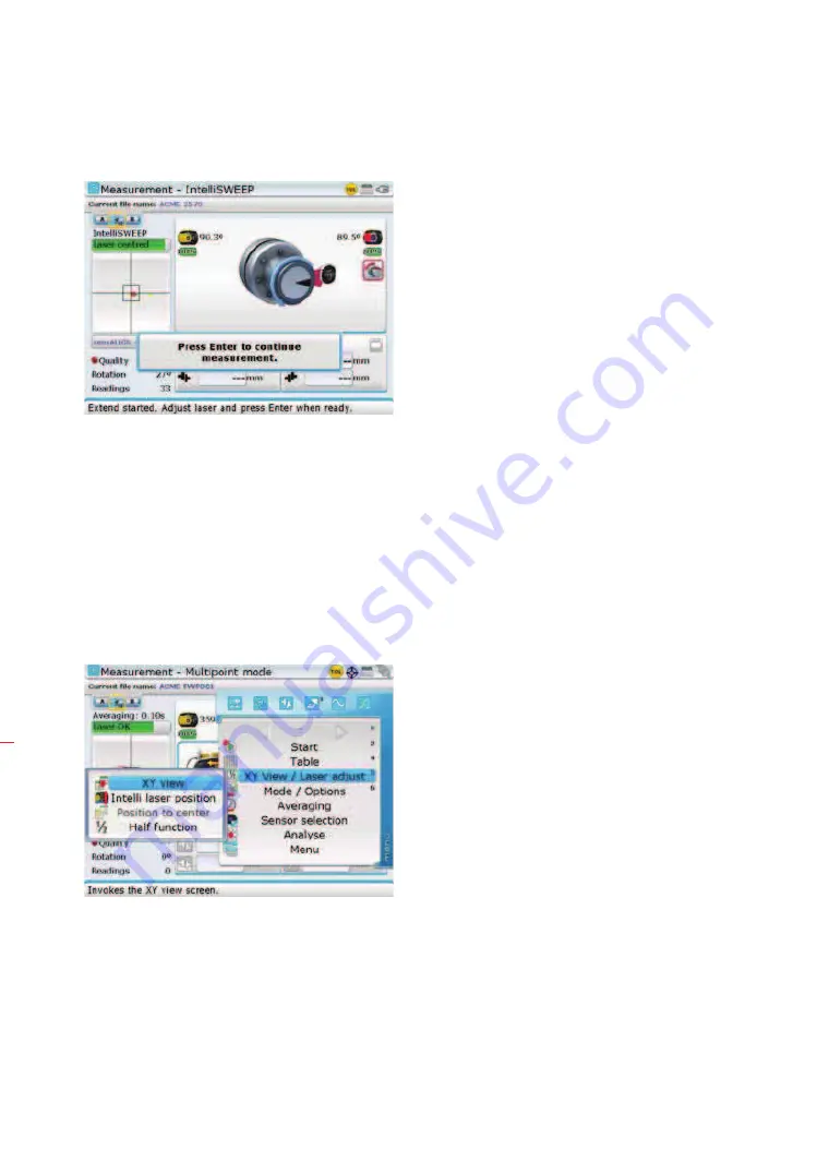
laser beam adjustment takes place in the “Measurement” screen, press
q
while on
this screen, then use the navigation keys and highlight the submenu item ‘XY View’.
Confirm selection by pressing
e
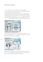
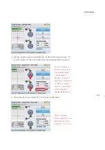
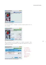
. The two sensor detector planes are displayed on
the “XY View” screen. Center the laser beam dots in both planes using both beam
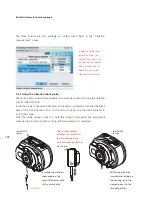
position thumbwheels. In some cases it may be necessary to move sensALIGN sensor
along the support posts or sideways by loosening the chain type bracket and slightly
rotating it.
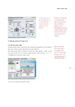
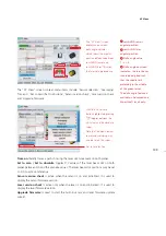
Note that the context menu
item ‘Averaging’ is present
when the measurement
mode is either Multipoint or
Static measurement.
Summary of Contents for ROTALIGN Ultra iS
Page 1: ...ROTALIGN Ultra iS Operating handbook Shaft alignment...
Page 11: ...ROTALIGN Ultra iS Shaft handbook 10 This page intentionally left blank...
Page 56: ...55 Horizontal shaft alignment 1 2 4 5 6...
Page 123: ...ROTALIGN Ultra iS Shaft handbook 122 Page intentionally left blank...
Page 141: ...ROTALIGN Ultra iS Shaft handbook 140 This page intentionally left blank...
Page 177: ...ROTALIGN Ultra iS Shaft handbook 176 Page intentionally left blank...
Page 207: ...ROTALIGN Ultra iS Shaft handbook 206 Page intentionally left blank...
Page 213: ...ROTALIGN Ultra iS Shaft handbook 212 Declaration of conformity...

