113
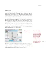
Half function
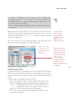
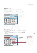
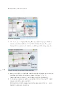
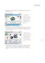
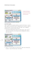
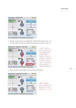
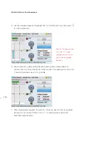
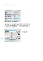
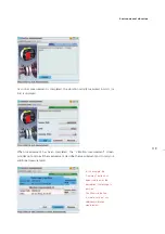
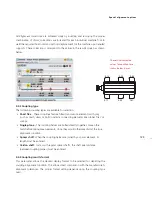
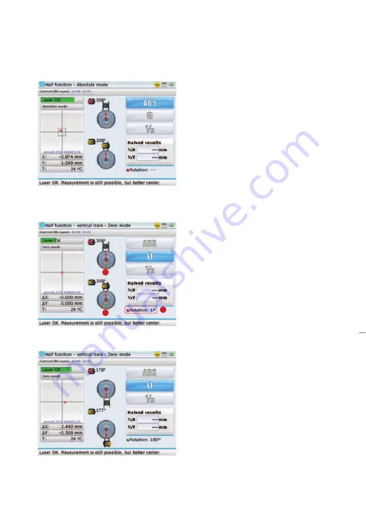
3. Use the navigation keys and highlight the ‘0’ half function icon then press
e
to confirm selection. The current laser dot position assumes the X,Y value 0,0.
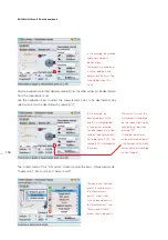
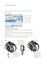
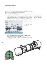
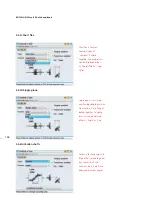
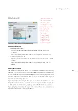
4. Now rotate the sensor through 180° as indicated on the screen.
Note that the position
to where the sensor and
laser should be rotated,
is marked green [
1
].
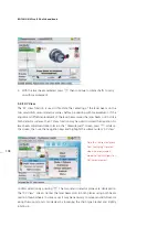
Rotation is carried out in
any direction - clockwise or
anti-clockwise [counter-
clockwise]. Also note the
rotation angle and its
corresponding button [
2
].
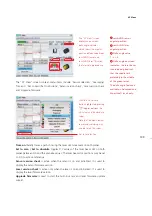
Note that the sensor
rotation angle button turns
green when the sensor
rotation is at 178° to 182°.
1
1
2
Summary of Contents for ROTALIGN Ultra iS
Page 1: ...ROTALIGN Ultra iS Operating handbook Shaft alignment...
Page 11: ...ROTALIGN Ultra iS Shaft handbook 10 This page intentionally left blank...
Page 56: ...55 Horizontal shaft alignment 1 2 4 5 6...
Page 123: ...ROTALIGN Ultra iS Shaft handbook 122 Page intentionally left blank...
Page 141: ...ROTALIGN Ultra iS Shaft handbook 140 This page intentionally left blank...
Page 177: ...ROTALIGN Ultra iS Shaft handbook 176 Page intentionally left blank...
Page 207: ...ROTALIGN Ultra iS Shaft handbook 206 Page intentionally left blank...
Page 213: ...ROTALIGN Ultra iS Shaft handbook 212 Declaration of conformity...

