ROTALIGN Ultra iS Shaft handbook
114
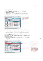
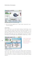
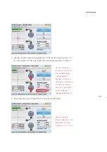
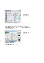
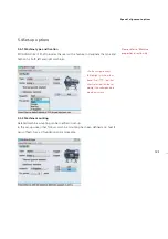
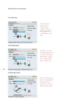
5. Use the navigation keys and highlight the ‘1/2’ half function icon, then press
e
to confirm selection.
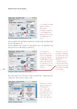
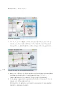
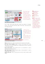
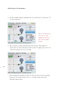
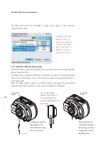
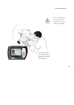
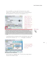
6. Now use the two yellow sensALIGN laser beam position thumbwheels to
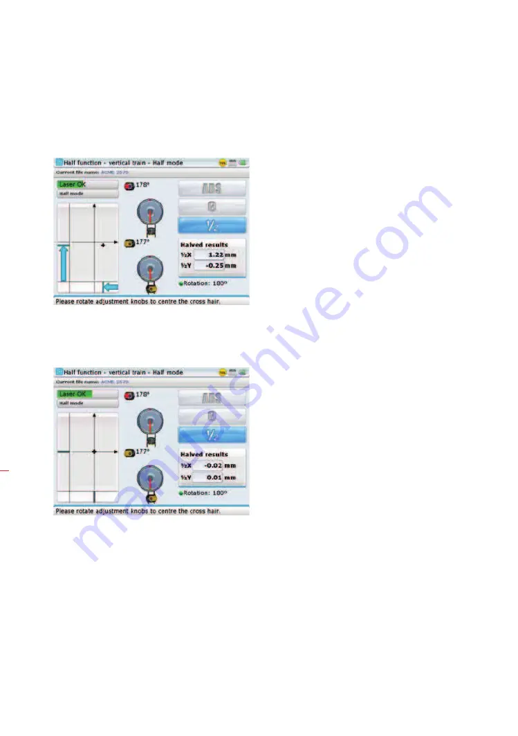
position the cross hair at the centre of the two axes. The displayed 1/2 X and 1/2
Y results should be as near 0.0 as possible
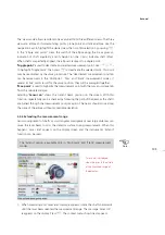
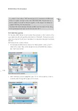
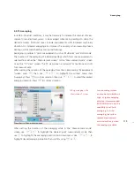
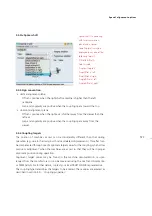
7. After attaining the required 1/2X and 1/2Y values [as near 0.0 mm as possible],
the laser is now on the shaft axis. Press
ß
to proceed with actual shaft
alignment measurements.
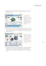
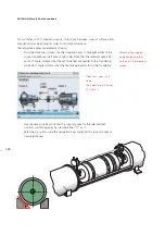
Note that the documented
1/2 X and 1/2 Y values
correspond to half the
∆
X
and
∆
Y values recorded
previously.
Summary of Contents for ROTALIGN Ultra iS
Page 1: ...ROTALIGN Ultra iS Operating handbook Shaft alignment...
Page 11: ...ROTALIGN Ultra iS Shaft handbook 10 This page intentionally left blank...
Page 56: ...55 Horizontal shaft alignment 1 2 4 5 6...
Page 123: ...ROTALIGN Ultra iS Shaft handbook 122 Page intentionally left blank...
Page 141: ...ROTALIGN Ultra iS Shaft handbook 140 This page intentionally left blank...
Page 177: ...ROTALIGN Ultra iS Shaft handbook 176 Page intentionally left blank...
Page 207: ...ROTALIGN Ultra iS Shaft handbook 206 Page intentionally left blank...
Page 213: ...ROTALIGN Ultra iS Shaft handbook 212 Declaration of conformity...


