ROTALIGN Ultra iS Shaft handbook
136
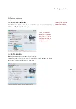
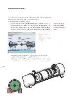
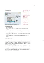
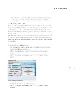
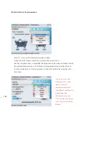
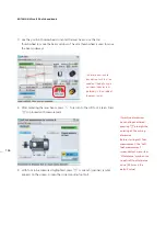
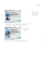
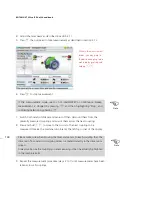
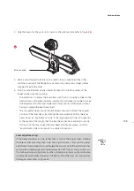
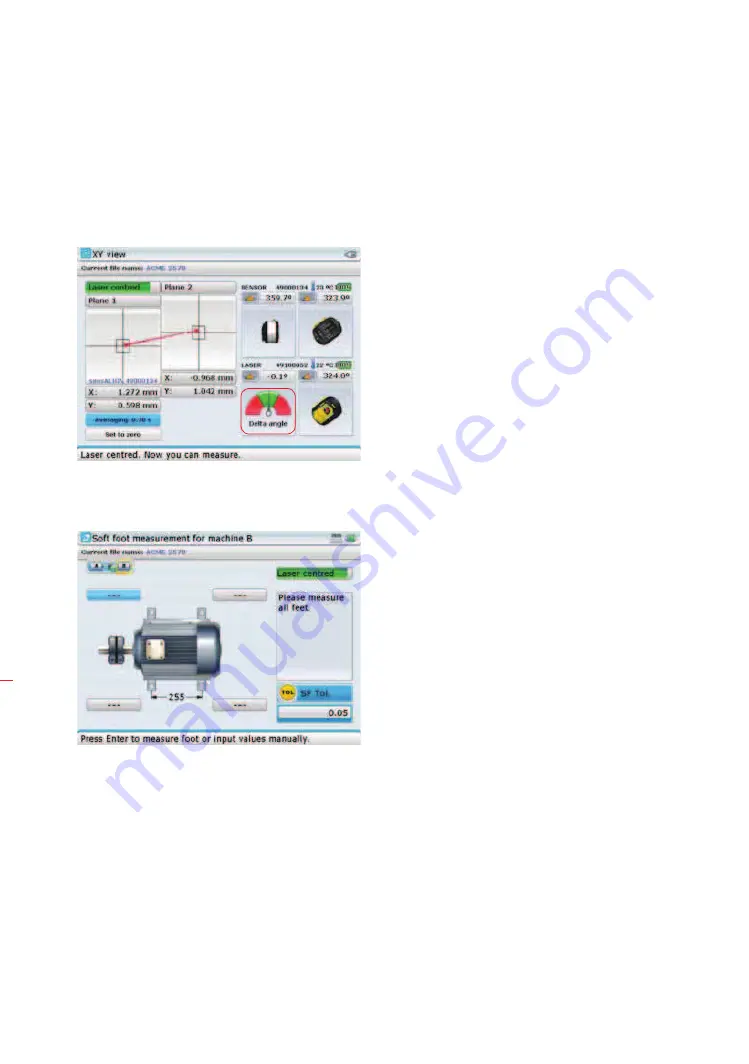
7. Use the position thumbwheels to center the laser beam. Use the top
thumbwheel to move the beam up/down. The side thumbwheel is used to move
the beam sideways.
8. After centering the laser beam, press
ß
to return to the soft foot screen. Press
e
to proceed with measurement.
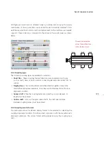
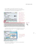
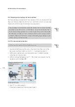
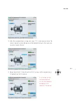
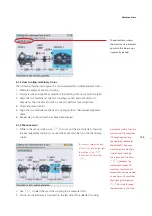
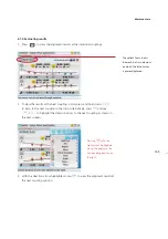
9. With foot to be measured highlighted, press
e
. A wrench (spanner) symbol
appears on the screen. Loosen the corresponding foot bolt.
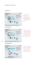
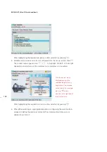
The laser beam should
be adjusted such that the
needle of the delta angle
on-screen indicator rests
preferably in the middle of
the green sector.
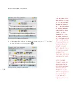
If machine dimensions
have not been entered,
pressing
e
prompts the
entering of the missing
dimension.
Before starting soft foot
measurement, the “Soft
foot measurement”
screen context menu item
‘SF tolerance’ may be used
to edit soft foot tolerance
value (0.05 mm is the
default value).
Summary of Contents for ROTALIGN Ultra iS
Page 1: ...ROTALIGN Ultra iS Operating handbook Shaft alignment...
Page 11: ...ROTALIGN Ultra iS Shaft handbook 10 This page intentionally left blank...
Page 56: ...55 Horizontal shaft alignment 1 2 4 5 6...
Page 123: ...ROTALIGN Ultra iS Shaft handbook 122 Page intentionally left blank...
Page 141: ...ROTALIGN Ultra iS Shaft handbook 140 This page intentionally left blank...
Page 177: ...ROTALIGN Ultra iS Shaft handbook 176 Page intentionally left blank...
Page 207: ...ROTALIGN Ultra iS Shaft handbook 206 Page intentionally left blank...
Page 213: ...ROTALIGN Ultra iS Shaft handbook 212 Declaration of conformity...


