ROTALIGN
®
Ultra iS Shaft handbook
150
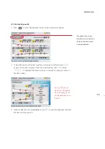
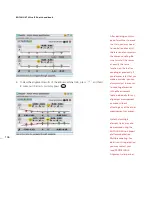
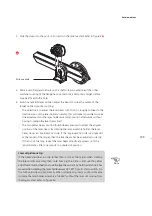
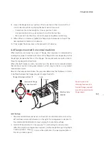
As soon as a single dot position has been achieved, do not touch the laser
position thumbwheels.
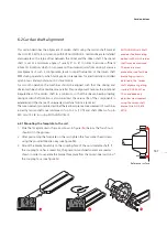
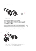
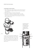
6.2.4. Adjusting the laser beam to machine’s rotational axis
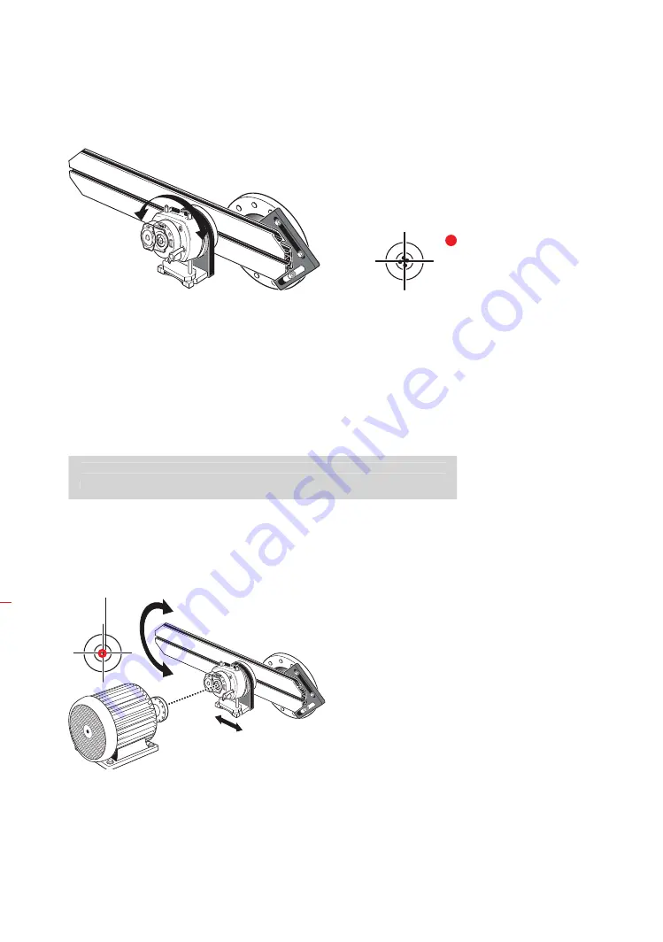
In this step, the laser holder assembly is adjusted on the bracket such that the laser
holder rotational axis is colinear with the rotational axis of machine to be aligned
(which could be a motor or a gearbox).
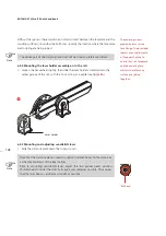
During this procedure, DO NOT touch the yellow laser beam position
thumbwheels.
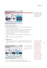
1. Carry out the vertical and horizontal adjustment of the laser holder assembly
by sliding it horizontally through the bracket rail and positioning it vertically by
rotating the bracket.
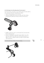
2. Repeat the above procedure until the laser beam strikes the center of the target
placed on the rotational axis of machine to be aligned.
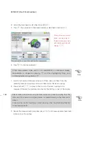
3. Once the laser beam has been centered on the target, tighten the faceplate on
the coupling face using the provided hexagon socket head screws.
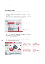
Note
During this procedure, DO NOT touch the yellow laser beam position
thumbwheels.
Laser dot
3c
Summary of Contents for ROTALIGN Ultra iS
Page 1: ...ROTALIGN Ultra iS Operating handbook Shaft alignment...
Page 11: ...ROTALIGN Ultra iS Shaft handbook 10 This page intentionally left blank...
Page 56: ...55 Horizontal shaft alignment 1 2 4 5 6...
Page 123: ...ROTALIGN Ultra iS Shaft handbook 122 Page intentionally left blank...
Page 141: ...ROTALIGN Ultra iS Shaft handbook 140 This page intentionally left blank...
Page 177: ...ROTALIGN Ultra iS Shaft handbook 176 Page intentionally left blank...
Page 207: ...ROTALIGN Ultra iS Shaft handbook 206 Page intentionally left blank...
Page 213: ...ROTALIGN Ultra iS Shaft handbook 212 Declaration of conformity...

