ROTALIGN
®
Ultra iS Shaft handbook
152
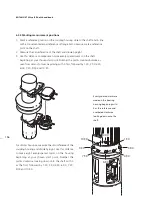
6.2.6 Set-up and measurement
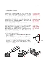
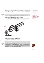
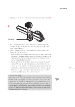
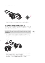
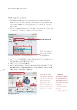
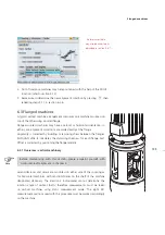
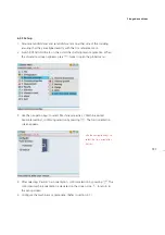
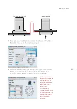
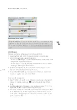
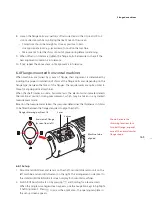
1. With sensALIGN laser, sensor and ROTALIGN Ultra iS computer switched on,
proceed to set up the machines (refer to sections 4.6 – 4.9). From the machine
set-up screen, highlight the coupling, then press
e
to access the “Coupling
type” screen.
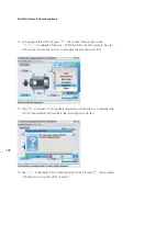
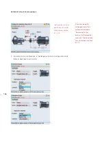
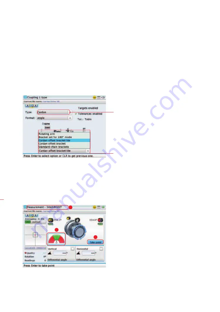
2. Select the coupling type ‘Cardan’ then navigate to the bottom box to select type
of bracket to be used from the drop down menu that opens.
3. Use
f
/
g
and highlight ‘Cardan offset bracket lite’. This is the option for
the cardan shaft bracket Lite ALI 2.874 SETIS.
4. Press
ß
or
e
to confirm selection.
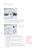
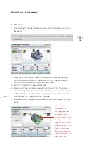
5. Slide the sensALIGN sensor dust cap to expose sensor lens then press
m
. The
laser beam location should be apparent in the “Measurement” screen, and the
‘Start’ button is automatically highlighted.
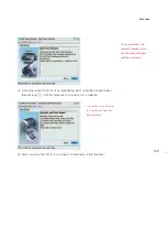
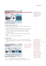
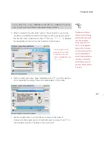
Selected coupling type
Bracket type drop down
menu to select ‘Cardan
offset bracket lite’
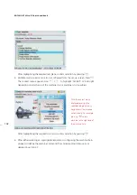
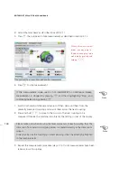
1 –
Designated
measurement mode for
the cardan bracket Lite
set ALI 2.874 SETIS with
ROTALIGN Ultra iS Shaft
Advanced
2 –
On-screen needle
indicator
3
– ‘Take point’ button’
When using the cardan
shaft alignment bracket Lite
ALI 2.874 SETIS, the system
selects the intelliPOINT
measurement mode.
To center the needle, both
laser and sensor must be at
the same rotational angle.
1
2
3
Summary of Contents for ROTALIGN Ultra iS
Page 1: ...ROTALIGN Ultra iS Operating handbook Shaft alignment...
Page 11: ...ROTALIGN Ultra iS Shaft handbook 10 This page intentionally left blank...
Page 56: ...55 Horizontal shaft alignment 1 2 4 5 6...
Page 123: ...ROTALIGN Ultra iS Shaft handbook 122 Page intentionally left blank...
Page 141: ...ROTALIGN Ultra iS Shaft handbook 140 This page intentionally left blank...
Page 177: ...ROTALIGN Ultra iS Shaft handbook 176 Page intentionally left blank...
Page 207: ...ROTALIGN Ultra iS Shaft handbook 206 Page intentionally left blank...
Page 213: ...ROTALIGN Ultra iS Shaft handbook 212 Declaration of conformity...

