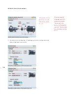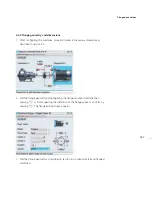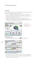
159
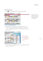
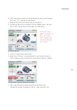
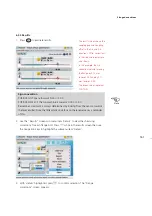
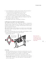
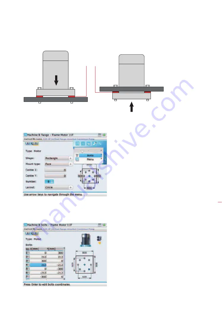
8. It may be necessary to edit the bolt coordinates. To do this, press
q
while in
the machine flange screen. The context menu appears.
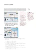
9. Use the navigation keys to highlight ‘Bolts’ then press
e
to confirm selection.
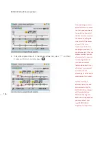
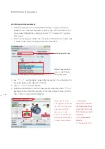
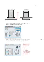
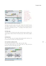
The bolt coordinates screen shown below opens. It shows the polar and
Cartesian coordinates of the bolts relative to the chosen shaft center.
face-mounted (standard)
reverse-mounted
shims
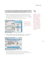
Use the navigation keys to
highlight the X/Y coordinate
of any bolt position. The
highlighted value may be
directly edited using the
data entry keys.
In this example, the
X-coordinate of bolt number
4 has been highlighted. The
corresponding bolt pattern
position also appears
highlighted.
Flanged machines
Summary of Contents for ROTALIGN Ultra iS
Page 1: ...ROTALIGN Ultra iS Operating handbook Shaft alignment...
Page 11: ...ROTALIGN Ultra iS Shaft handbook 10 This page intentionally left blank...
Page 56: ...55 Horizontal shaft alignment 1 2 4 5 6...
Page 123: ...ROTALIGN Ultra iS Shaft handbook 122 Page intentionally left blank...
Page 141: ...ROTALIGN Ultra iS Shaft handbook 140 This page intentionally left blank...
Page 177: ...ROTALIGN Ultra iS Shaft handbook 176 Page intentionally left blank...
Page 207: ...ROTALIGN Ultra iS Shaft handbook 206 Page intentionally left blank...
Page 213: ...ROTALIGN Ultra iS Shaft handbook 212 Declaration of conformity...

