ROTALIGN Ultra iS Shaft handbook
24
2.4.1 Understanding the beam adjustment LEDs
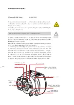
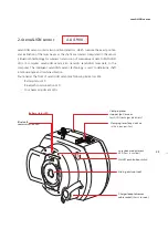
The four beam adjustment LEDs provide additional help when adjusting the laser
beam position on sensALIGN sensor position detectors. The LEDs indicate the angle
and position at which the laser beam enters the sensor. The LEDs blink either red
or green depending on the angle at which the laser beam strikes the sensor. Green
indicates a small angle while red indicates a large angle that must be corrected before
beginning measurement.
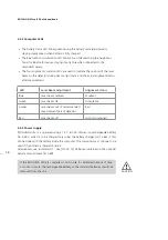
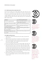
Activity
Laser beam adjustment LEDs
Switch on sensALIGN sensor
All four LEDs light up red then continue
to blink every two seconds
Laser beam striking dust cap [laser
off]
All four LEDs blink red every second
Laser beam entering sensor with a
large angular deviation
One or more LEDs blinks red every
second
Laser beam entering sensor with
little or negligible angular deviation
but with an offset
All four LEDs blink green twice every
second
Laser beam entering sensor with
neither appreciable angular deviation
nor offset
All four LEDs blink green every second
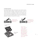
2.4.2 Adjusting the laser beam
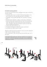
1. With the lens covered, let the laser beam strike the centre of the sensALIGN
sensor dust cap.
2. Slide the dust cap to open the lens. Observe the four laser beam adjustment
LEDs while adjusting the laser beam using the vertical and horizontal beam
positioning thumbwheels. The thumbwheels are used to adjust both the
horizontal and vertical laser beam angles.
3. Carry out this adjustment until all four LEDs are blinking green once every second.
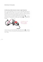
4. If the LEDs are blinking green twice every second, the angle at which the laser
beam enters the sensor is correct, but an offset is present. Eliminate the offset
by sliding back the sensALIGN sensor dust cap to cover the lens, then loosen the
chain type bracket supporting sensALIGN sensor and move the sensor sideways.
At the same time, release the sensALIGN sensor clamping levers and move the
sensor upwards and downwards until the laser beam is centred on the dust cap.
During this adjustment, DO NOT touch sensALIGN laser.
5. Open the lens by sliding the dust cap and check the blinking of the four LEDS.
If all four are blinking green once every second, then the laser beam has been
correctly centred.
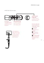
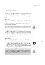
All four LEDs blink red every
second when the laser
beam enters the sensor with
a large angular deviation
and offset.
When one or more LEDs
blinks red every second, the
laser beam is entering the
sensor with a large angular
deviation that must be
corrected.
When all four LEDs are
blinking green twice every
second, the laser beam is
entering the sensor without
an appreciable angular
deviation. In this case,
only the offset needs to
be corrected (see step 4
opposite).
Summary of Contents for ROTALIGN Ultra iS
Page 1: ...ROTALIGN Ultra iS Operating handbook Shaft alignment...
Page 11: ...ROTALIGN Ultra iS Shaft handbook 10 This page intentionally left blank...
Page 56: ...55 Horizontal shaft alignment 1 2 4 5 6...
Page 123: ...ROTALIGN Ultra iS Shaft handbook 122 Page intentionally left blank...
Page 141: ...ROTALIGN Ultra iS Shaft handbook 140 This page intentionally left blank...
Page 177: ...ROTALIGN Ultra iS Shaft handbook 176 Page intentionally left blank...
Page 207: ...ROTALIGN Ultra iS Shaft handbook 206 Page intentionally left blank...
Page 213: ...ROTALIGN Ultra iS Shaft handbook 212 Declaration of conformity...


