39
4.5 Mount sensALIGN laser and sensor
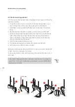
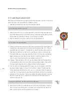
Mount sensALIGN laser on the support posts of the bracket fixed on the shaft of the
left machine (usually reference machine), and sensALIGN sensor on the support posts
of the bracket fixed on the shaft of the right machine (usually moveable machine)
– as viewed from normal working position. Before mounting both sensALIGN laser
and sensor, make sure that the sure that the yellow clamping levers are in the open
position by placing them to the front. This enables components to slide onto the
support posts.
Fix both sensALIGN laser and sensor onto the respective support posts by locking the
yellow clamping levers. Lock the levers by pushing them backwards until they rest on
the stoppers. Ensure that the laser can pass over or through the coupling and is not
blocked.
Both sensALIGN laser and sensor should be at the same height, as low as possible, yet
just high enough for the beam to clear the coupling flange. They should also visually
appear to be rotationally aligned to each other.
Make the final adjustments, loosening the brackets slightly if necessary, then rotating
them and retightening.
Clamping levers in the
open position
Clamping levers in the
open position allows
sensALIGN laser or sensor
to slide onto the support
posts.
Locking the clamping
levers by pushing them
against the stoppers fixes
sensALIGN laser or sensor
onto the support posts.
Horizontal shaft alignment
Clamping lever in the
lock position
Laser
Sensor
Mount just high enough
to clear coupling
Summary of Contents for ROTALIGN Ultra iS
Page 1: ...ROTALIGN Ultra iS Operating handbook Shaft alignment...
Page 11: ...ROTALIGN Ultra iS Shaft handbook 10 This page intentionally left blank...
Page 56: ...55 Horizontal shaft alignment 1 2 4 5 6...
Page 123: ...ROTALIGN Ultra iS Shaft handbook 122 Page intentionally left blank...
Page 141: ...ROTALIGN Ultra iS Shaft handbook 140 This page intentionally left blank...
Page 177: ...ROTALIGN Ultra iS Shaft handbook 176 Page intentionally left blank...
Page 207: ...ROTALIGN Ultra iS Shaft handbook 206 Page intentionally left blank...
Page 213: ...ROTALIGN Ultra iS Shaft handbook 212 Declaration of conformity...

