background image

ROTALIGN Ultra iS Shaft handbook

82

4.16 Alignment completion 

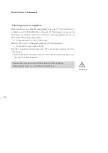
After completion of an alignment measurement or job, press 

e

 and hold down for 

a moment to switch ROTALIGN Ultra iS computer off. Alternatively one may use the 

global  menu  combination  ‘Quit’/’Turn  off  device’.  If  the  measurement  file  has  not 

been saved, the following query appears: 


‘Do you really want to turn off the system?’ 

Selecting ‘Yes’ to turn off the system prompts the following question: 


‘Do you want to save changes in file?’ 

Save file if required for record and analysis. If it is not required, selecting ‘No’ turns 

off the system. 


Switch both sensALIGN laser and sensor off and slide back both laser and sensor 

dust caps to cover the apertures. 

Remove the components from the shafts and store them in the case. 

Replace guards before you switch the machine back on.

WARNING

Remove the components from the shafts and store them in the case. 

Replace guards before you switch the machine back on.

Summary of Contents for ROTALIGN Ultra iS

Page 1: ...ROTALIGN Ultra iS Operating handbook Shaft alignment...

Page 2: ...reading PR FTECHNIK Alignment Systems GmbH Freisinger Str 34 85737 Ismaning Germany Tel 49 89 99616 0 Fax 49 89 99616 100 Email info pruftechnik com Edition April 2014 Part number DOC 40 200 en Firmwa...

Page 3: ...aking it possible to measure grossly misaligned machines or those with long couplings Both sensor and laser incorporate Micro Electro Mechanical System MEMs allowing the measurement of component rotat...

Page 4: ...1 Starting the shaft alignment application 35 4 2 Horizontal machine alignment preparing for the alignment procedure 36 4 3 Check soft foot 37 4 4 Mount the brackets 37 4 5 Mount sensALIGN laser and s...

Page 5: ...o higher version 171 Chapter 8 ROTALIGN Ultra iS Shaft configuration 177 8 1 Configuration 177 8 2 User accounts 191 8 3 Creating templates 198 8 4 Deleting created templates from the program manager...

Page 6: ...ALI 4 202 ROTALIGN Ultra iS computer including ROTALIGN Ultra iS rechargeable battery ALI 4 603 ROTALIGN Ultra iS stand ALI 4 201 ALI 4 910 sensALIGN laser sensALIGN rechargeable battery ALI 4 960 is...

Page 7: ...SB cable ALI 12 503 USB peripheral devices cable ALI 12 651 I AC power supply charger universal for powering and charging ROTALIGN Ultra iS computer and rechargeable battery ALI 4 921 2 ALI 4 651 I AL...

Page 8: ...2 172 ALI 2 173 ALI 2 174 and storage pouch ALI 3 590 200 ALI 2 905 Lens cleaning cloth ALI 3 588 Tape measure mm inch DOC 40 100 en ROTALIGN Ultra iS Shaft pocket guide DOC 40 200 en ROTALIGN Ultra...

Page 9: ...00 CD ALIGNMENT CENTER CD ALI 4 741 ROTALIGN Ultra Advanced Shaft Firmware registration certificate not shown ALI 4 905 Vibration check probe ALI 4 451 USB memory stick 0 0739 1055 Allen key 2 5 mm AL...

Page 10: ...615 Desktop charging station for ROTALIGN Ultra iS rechargeable battery ALI 4 615 SET Desktop charging station set for ROTALIGN Ultra iS rechargeable battery includes Desktop charging station ALI 4 6...

Page 11: ...ROTALIGN Ultra iS Shaft handbook 10 This page intentionally left blank...

Page 12: ...must be followed in order to avoid damage to equipment This symbol denotes information which must be followed in order to avoid personal injury Numbers in red circles indicate the corresponding operat...

Page 13: ...r care should be taken to avoid staring into the beam Do not insert any optical devices into the beam path The red LED on the front of sensALIGN laser illuminates whenever the laser beam is emitted CA...

Page 14: ...tions pursuant to Laser Notice No 50 dated June 24 2007 DO NOT STARE INTO BEAM U N L IM ITED PRECIS I O N s e n sALIGNTM L a s e r OPEN LASER RADIATION DO NOT STARE INTO BEAM P 1mW pulse 400 s 635nm C...

Page 15: ...easy to follow icons and comprehensive on screen menus and hint texts that enable even first time users to operate the computer without difficulty The label opposite is on the back of ROTALIGN Ultra i...

Page 16: ...ction To switch on off press and hold e the On Off Enter key briefly The Up key is used as a back return key taking user to previously selected function or to exit current screen The CLR Clear key is...

Page 17: ...ended measurement part of detector Bad Red Laser beam off Grossly misaligned 2 2 3 Power supply ROTALIGN Ultra iS is powered using a 7 2 V 6 0 Ah Lithium ion rechargeable battery ALI 4 603 which is to...

Page 18: ...ing depending on power supply source out The reverse procedure is used to mount back the recharge able battery or the battery housing back into the computer Lift battery housing or rechargeable batter...

Page 19: ...just above the pins and the arrow on the latching nipple on the charger housing To dismount a plug push the latching nipple in the forward direction 1 as indicated by the arrow on it and hold then pus...

Page 20: ...ocket The red dot on the charger plug must match the red dot on the battery socket 1 3 2 1 2 3 Note that available cables may be connected to the corresponding numbered sockets as follows ALI 4 921 2...

Page 21: ...ng possible contamination Information regarding the battery status the rotational angle the temperature and the serial number of the sensALIGN laser are transmitted through the laser beam into sensALI...

Page 22: ...aser beam active LED Switch on Lights up green for 3 seconds when battery run time is 10 hrs Blinks green every 3 seconds when battery run time is between 5 10 hrs Blinks red every 3 seconds when batt...

Page 23: ...either sensALIGN laser or sensor Used batteries should be disposed of in an environmentally sound manner Used batteries should be disposed of in an environmentally sound manner The position and remova...

Page 24: ...intelligent sensALIGN sensor technology is used to determine shaft rotational angle and machine vibration Positioned at the front of sensALIGN sensor are following indicator LEDs Battery status LED B...

Page 25: ...r laser beam adjustment LEDs while adjusting the laser beam using the vertical and horizontal beam positioning thumbwheels The thumbwheels are used to adjust both the horizontal and vertical laser bea...

Page 26: ...though the ROTALIGN Ultra iS Shaft system is essentially maintenance free the following points should be observed The calibration accuracy of the system components should be checked every two years as...

Page 27: ...ure that stray magnetic fields do not affect the avionics in aircraft the aviation industry has put forward stringent regulations for air transportation of magnetic material The magnetic field strengt...

Page 28: ...ry status Other shaft alignment components such as brackets and other accessories 3 2 Obtaining alignment readings in quick intelligent steps 3 2 1 Mount components on machine train to be measured Bot...

Page 29: ...ing Program Manager screen then press e to confirm selection 3 2 5 Enter machine dimensions The machine set up screen is accessed by pressing d You may use the global menu see section 3 2 9 items Conf...

Page 30: ...t is centred on the square target then rotate shafts Refer to section 4 11 for details on taking measurements 3 2 7 View alignment results After measurement press RES to view the alignment results The...

Page 31: ...y use may be made of the data entry keys which provide navigation shortcuts All context menu items are labelled with digits for quick access The required menu item is accessed directly by pressing the...

Page 32: ...n the following two forms a configuration global menu that appears within the program manager a complete global menu covering all menu items this appears within the Shaft application The global menu m...

Page 33: ...nds prompts the turn off system dialog Pressing e for approximately 7 seconds resets the system For machine trains with more than one coupling position pressing either h or i long enough moves the vie...

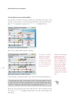
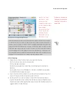
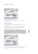
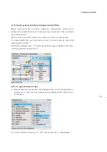
Page 34: ...entation of the machine can be altered by pressing either h or i Pressing d twice while in set up zooms the machine train out and in again When entering file or element names pressing o cycles through...

Page 35: ...the data entry keys or any of the navigation keys 3 3 5 Results Pressing f or g while in results cycles the results between vertical V horizontal H and both H V Pressing f or g long enough zooms out...

Page 36: ...red licence code 4 1 1 Starting the licence manager After switching ROTALIGN Ultra on use the navigation keys to highlight Configuration icon Press e to access this option then use the navigation keys...

Page 37: ...Alignment application prepare the machines as described below Switch off the machines before commencing work and make sure that they cannot be started accidentally 4 2 1 Solid flat foundation A solid...

Page 38: ...sensor separations Note that over very large distances the shafts and coupling may sag and the machines may need to be aligned to take this into account Refer to the machine manufacturer s specificati...

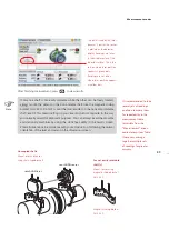
Page 39: ...he diagram if the shaft is larger than the bracket width insert the chain into the frame from the outside 4 Catch the chain loosely on the anchor peg 5 Turn the bracket thumbscrew to tighten the assem...

Page 40: ...the levers by pushing them backwards until they rest on the stoppers Ensure that the laser can pass over or through the coupling and is not blocked Both sensALIGN laser and sensor should be at the sa...

Page 41: ...elow appears The above screen will appear only if the customization option Resume policy has been set to Resume files manually See customization described in section 8 1 10 If desired elements in the...

Page 42: ...propriate data entry keys The editing box appears as soon as the first key is pressed Confirm the entered value by pressing either e or The highlight springs to the next empty dimension box If necessa...

Page 43: ...need to edit the value use the navigation keys to highlight it and edit it directly using the data entry keys 4 7 3 RPM revolutions per minute The default value is 1500 1800 if set to US units Should...

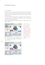
Page 44: ...Use the navigation buttons to highlight either button confirming selection by pressing e The toggle button is used change the orientation of the selected machine along the shaft axes The rotate button...

Page 45: ...Select type of mounting from the drop down menu that appears using f g Confirm selection by pressing either e or Press and hold down o while observing the status indicator at the bottom right corner o...

Page 46: ...tion of the flange requires to be entered To enter flange location use the navigation keys to place cursor on the Location box then press e Select location from the drop down menu that appears using f...

Page 47: ...to access the thermal growth screen Alternatively use either f g to highlight Thermal growth confirming selection by pressing e Use h i to cycle through the feet positions highlighting the value boxe...

Page 48: ...es enabled check box With either box highlighted press e to check or uncheck the respective box Targets and tolerances are activated only when the respective box is checked To enter coupling target va...

Page 49: ...er coupling target value highlight the value box using the navigation keys With the value box highlighted enter target value directly using the data entry keys Press e or to confirm entry With the Typ...

Page 50: ...he coupling diameter used in the Set up screen Sign convention displays the definition and graphic depiction of sign convention Left Right Both used to select the direction considered when analyzing c...

Page 51: ...als the context menu shown below Press 3 to display the system tolerance table Alternatively highlight Tolerance using f g and confirm selection by pressing e The menu item Machine properties is used...

Page 52: ...maximum tolerance values Use the navigation keys to highlight the Format box Access the drop down menu by pressing e Use f g to highlight the required format confirming selection by pressing e or Usin...

Page 53: ...screen then use f g to highlight the context menu item Flip machines 2 Press e to confirm selection A Flip machines hint screen appears In this example the machine set has been mounted next to a wall...

Page 54: ...er is mounted on the machine on the left then check the distance between the sensor to coupling center Note The hint reminds the user that the laser must always be mounted on the left machine as viewe...

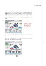
Page 55: ...hen the laser beam is correctly centered on the sensor and you may proceed with measurement section 4 11 6 If however the laser beam is still not correctly centered readjust the laser beam using the y...

Page 56: ...55 Horizontal shaft alignment 1 2 4 5 6...

Page 57: ...n the screen Press q then use f g to highlight the context menu item Sensor selection Confirm selection by pressing e The sensor selection window opens Use f g to highlight Scan for wireless devices t...

Page 58: ...am until the Laser centred message appears in the laser beam adjustment pane sensALIGN sensors that have been detected are stored in the system and always appear in the sensor selection screen Sensors...

Page 59: ...Details on the other modes can be found in section 5 1 Measurement modes Application Measurement mode Standard Shaft Measurement mode Advanced Expert Shaft Standard machines Continuous Sweep IntelliSW...

Page 60: ...splayed if selected under the measurement screen context menu item Measurement options Measurement quality is an intelligent feature based on several measurement and environmental criteria The resulti...

Page 61: ...ribbed collar of the right angled connector and carefully pull it out of the sensALIGN sensor charger adapter cable socket Note that sensALIGN laser may also be powered through the ROTALIGN Ultra iS...

Page 62: ...d 4 13 Results Once measurement is completed press RES to view alignment results ROTALIGN Ultra iS intelligent features guide the user to obtain reliable alignment results The above display shows the...

Page 63: ...only one pair of feet is fixed an optimized centerline will be displayed for all remaining unfixed feet Note that machine feet are displayed in the results screen only when the Stationary machine box...

Page 64: ...the option that should be used when actually performing alignment corrections If the option Show correction arrows is activated coloured tolerance arrows appear at the feet positions as further help i...

Page 65: ...length both stationary and moveable machines are displayed with equal size Equal fixation distance machines are displayed with equal separation between front and back feet for all machines in the tra...

Page 66: ...is available within the Results Move and Move simulator screens After obtaining measurement results press q then use the navigation keys and highlight View Rotate view With Rotate view highlighted pre...

Page 67: ...hows the current orientation after the Rotation view function was applied In the screen on the right the machine designated stationary is now on the right hand side Note that the vertical coupling gap...

Page 68: ...ecessary 4 14 Align machine To align your machine you need to move it vertically by shimming the feet and horizontally by shifting it sideways You can perform these operations in either order or simul...

Page 69: ...t menu item Move simulator Confirm selection by pressing e The Move simulator screen opens To effectively use the Move simulator it is necessary to set the required machine movement step This value is...

Page 70: ...dance with the set step value Pressing f moves the machine upwards in vertical view or away from viewer in horizontal view by the movement value factor Pressing g moves the machine downwards in vertic...

Page 71: ...tate view Details More Details and Options More Options Selecting Reset values and confirming selection resets the simulator to the original result values Selecting Rotate view allows the simulation o...

Page 72: ...data entry keys to edit this value The editing box appears as soon as any data entry key is pressed After editing the movement value press e or to confirm entry Press to return to the Move simulator...

Page 73: ...en to proceed with live Move Live Move may be stopped via the Move measurement screen context menu item Stop Use f g to highlight the menu item Stop then confirm selection by pressing e Live horizonta...

Page 74: ...oosened suspect soft foot iii Use the vertical foot correction values to shim BOTH front and back feet as required Positive feet values indicate that the feet are high and therefore shims should be re...

Page 75: ...viewer Do NOT attempt to move the machine using heavy sledgehammer blows This can cause bearing damage and also produce inaccurate Move results Jack bolts on the feet or other mechanical or hydraulic...

Page 76: ...a measurement file was saved during set up the results may be saved after measurement as follows With results displayed press q and use the navigation keys to highlight File Save confirming selection...

Page 77: ...ess q while on set up screen The context menu appears Use the navigation keys to highlight File followed by Save Press e to confirm selection The Save document as screen appears and file may be saved...

Page 78: ...he machine configuration overview screen then press q The context menu appears Use f g to highlight the context menu item Report c With Report highlighted press e to confirm selection The Report scree...

Page 79: ...display The report has now been saved onto the memory stick as a PDF copy and may be transferred to a PC for archiving or printing to any Windows compatible printer Note that the submenu items may be...

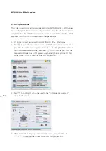
Page 80: ...503 Depending on your printer interface you may require an A to B USB cable Most printers are delivered with this USB cable which is also readily available from most electronic goods dealers b Press...

Page 81: ...ings must be configured to match the available printer Note that if the available printer has been configured correctly pressing eprints report Use h i to switch between the two panes Use f g to selec...

Page 82: ...81 f Confirm selection using the Print screen context menu item OK g When ready press e to print report If no report is printed check the printer set up described in section 8 1 5 Saving and printing...

Page 83: ...system Selecting Yes to turn off the system prompts the following question Do you want to save changes in file Save file if required for record and analysis If it is not required selecting No turns o...

Page 84: ...ement modes are accessed via the measurement screen Press m to access the measurement screen While on this screen press q The context menu appears Use f g to highlight the context menu item Measuremen...

Page 85: ...ironmental vibration resulting in extremely precise measurement results The method is used to measure all standard machines Other IntelliSWEEP features include Intelligent filtering and averaging of r...

Page 86: ...re available only if ROTALIGN Ultra Advanced Shaft firmware has been installed and licenced in the ROTALIGN Ultra iS computer This is done by acquiring the ROTALIGN Ultra Advanced Shaft firmware certi...

Page 87: ...ation speed e g releasing and re applying a break during the rotation Rotation direction change in the measurement rotational direction Rotational speed how fast sensALIGN sensor shaft is rotated duri...

Page 88: ...laser and sensor at an angular rotation corresponding to the actual position of the components as mounted on the shafts Take next measurement point by pressing e Note that after e has been pressed the...

Page 89: ...s are taken when the laser beam passes through the middle sector of the detector After centering the laser beam as described in section 4 10 rotate the shaft supporting one of the measurement heads sa...

Page 90: ...pears as yellow dots Note If only one shaft is not easily rotatable while the other can be freely rotated always y mount the sensor on the nonrotatable shaft use the magnetic sliding bracket ALI 2 230...

Page 91: ...center of the sensor lens Measurement is taken when the laser beam strikes the center of the detector After centering the laser beam as described in section 4 10 the Take point button appears on the...

Page 92: ...ame arc position as the initial point and the beam coordinates are stable With the Take point button highlighted press e to take second measurement point Rotate either head to the next measurement pos...

Page 93: ...readings into ROTALIGN Ultra iS Shaft values 1 Press m to open the measurement screen With the measurement screen open press q The context menu appears Use f g to highlight the context menu item Measu...

Page 94: ...values press e The cursor highlights the 12 00 o clock rim value box Alternatively use the Dial gauge measurement screen context menu item Start to begin entering the dial gauge values Measurement mod...

Page 95: ...by pressing either e or The next empty entry box is highlighted You may use the navigation keys to cycle through the value entry boxes 7 To view ROTALIGN Ultra iS Shaft gap and offset coupling values...

Page 96: ...view foot results Pressing RES reveals the results screen showing feet positions if the dimensions have already been entered If dimensions are missing the set up screen prompting dimensions appears M...

Page 97: ...le screen use f g to highlight measurement whose values are to be converted into dial indicator readings then press q Use f gto highlight the item Gauge values from the context menu that appears On co...

Page 98: ...ext menu item Table Press e to view the measurement table Note that if a dial gauge set up already exists within the measurement table dial indicator readings for any highlighted measurement will be d...

Page 99: ...cular measurement was taken labels used calibration due dates for the sensALIGN sensor used and used sensALIGN laser serial number Up to 50 measurements can be stored in a measurement table Changes ma...

Page 100: ...a measurement proceed as follows 1 Access the measurement table from the measurement screen by pressing q while in the measurement screen From the context menu that appears use f g to highlight Table...

Page 101: ...i to highlight OK then press e to accept label 5 2 2 1 Editing label In this example measurement no 2 which has been highlighted and checked is to be assigned a label If desired customized labels may...

Page 102: ...easurement permanently 5 2 4 Identifying history labels To find out how many different labels have been assigned in measurement history table proceed as follows 1 With measurement table displayed pres...

Page 103: ...ars showing all labels used in the file 3 To identify the measurement related to a particular label use f g to highlight the respective label then press q Use f g to highlight the context menu item Hi...

Page 104: ...nt use the Measurement screen context menu item Stop table to access the measurement table With the particular measurement highlighted press q then use f g to highlight the menu item Edit points Press...

Page 105: ...e bold dot and deviates by 0 048 mm The standard deviation SD is 0 030 In this example the deactivated point is the one that was highlighted in the previous example The point appears as a clear circle...

Page 106: ...int with the maximum deviation from the calculated ellipse Selecting Sensor on shows the current beam position on the screen With this function repeatability can be checked by following the path of th...

Page 107: ...tension 3 Readjust the beam into the target squares using the two yellow sensALIGN laser horizontal and vertical position thumbwheels then press e or The adjusted beam position is taken as the end poi...

Page 108: ...rt ROTALIGN Ultra iS Shaft levels IntelliEXTEND is available only in IntelliSWEEP measurement mode 1 When taking measurement using intelliSWEEP and the laser beam approaches the end of the detector su...

Page 109: ...used to correct the deviation As laser beam adjustment takes place in the Measurement screen press q while on this screen then use the navigation keys and highlight the submenu item XY View Confirm s...

Page 110: ...o display the laser firmware version Upgrade firmware is used to start the built in sensor and laser firmware update wizard The XY View screen displays an on screen delta angle indicator which shows t...

Page 111: ...en measuring shafts with gross misalignment or angular misalignment over large distances Intelli laser position is used as follows 1 As laser beam adjustment takes place in the Measurement screen pres...

Page 112: ...enu item Position to center is now active This is the default laser beam adjustment procedure but it becomes inactive when intelli laser position is activated and used In this example the rotational a...

Page 113: ...fts is one such example The half function procedure would be as follows 1 As laser beam adjustment takes place in the Measurement screen press q while on this screen then use the navigation keys and h...

Page 114: ...he sensor through 180 as indicated on the screen Note that the position to where the sensor and laser should be rotated is marked green 1 Rotation is carried out in any direction clockwise or anti clo...

Page 115: ...o position the cross hair at the centre of the two axes The displayed 1 2 X and 1 2 Y results should be as near 0 0 as possible 7 After attaining the required 1 2X and 1 2Y values as near 0 0 mm as po...

Page 116: ...marily for live Move and soft foot measurement When setting the duration of the averaging from the corresponding Measurement screen press q then use f g to highlight the context menu item Averaging Pr...

Page 117: ...o highlight XY view Press e to confirm selection The XY view screen appears with the averaging box highlighted Press e to expand the drop down menu then use f g to select the desired averaging duratio...

Page 118: ...nually by pressing e or automatically when shafts are rotated Whether measurement points are taken manually by pressing e or automatically in Multipoint measurement mode automatic collection of measur...

Page 119: ...and mounted on the machine press m to access the Measurement screen Press q to display the context menu items Use the navigation keys and highlight Analyze Vibration meas Press e to confirm selection...

Page 120: ...the Vibration measurement screen provides options to exit the measurement describe the measurement and to carry out additional measurements In this example the Comment button has been used to enter th...

Page 121: ...probe securely locked in hold the probe firmly against the appropriate measurement location on the machine until measurement is completed In addition to the three button functions the context menu ite...

Page 122: ...ransferring vibration measurement results via Bluetooth to ROTALIGN Ultra iS computer Exercise CAUTION when carrying out vibration measurement using the vibration check probe CAUTION Vibration check p...

Page 123: ...ROTALIGN Ultra iS Shaft handbook 122 Page intentionally left blank...

Page 124: ...ines 5 4 2 Machine mounting Detailed machine mounting can be specified in set up In the set up screen that follows machine mounting has been defined as 6 feet 3 pairs of feet has a V foundation and is...

Page 125: ...e that the default angle is 45 and a 0 angle indicates that the machine feet are parallel to the foundation while a 90 angle indicates that the feet are perpendicular to the foundation Use the data en...

Page 126: ...ike rubber tires or springs Single plane The coupling halves are bolted directly together Loosen the bolts before taking measurements since they would otherwise distort the true alignment condition Sp...

Page 127: ...oupling results may be displayed either as Angle Offset or Gap Offset Single plane is for simple non flexible couplings which are usually just two flanges bolted together Coupling results may be displ...

Page 128: ...can be compensated through use of alignment target values for the coupling which allow precise misalignment when the machines are at rest so that they will be in proper alignment position during opera...

Page 129: ...endix In ROTALIGN Ultra iS Shaft the live tolerance function can be activated or deactivated from either the coupling properties window or the tolerances window When the function is checked active the...

Page 130: ...tolerances Use f g and highlight User tolerances With User tolerances highlighted press e to access the coupling tolerance screen used to edit tolerance values RPM value box Alignment tolerances are d...

Page 131: ...Coupling tolerances screen then the values revert to those entered in the dimensions set up screen Recalculate tolerances works out tolerances based on the coupling diameter entered in the dimensions...

Page 132: ...is is called the machine s thermal growth ROTALIGN Ultra iS Shaft may be used to calculate thermal growth compensation if no other values are available Thermal growth is calculated from the material c...

Page 133: ...boxes and enter directly the ambient temperature the machine running temperature and the distance from machine base or shimming plane to the shaft centerline using the data entry keys The context menu...

Page 134: ...ft soft foot function With the sensALIGN laser and sensor mounted on the shaft in the usual way the system is able to sense any machine movement when the machine bolts are loosened individu ally By en...

Page 135: ...oft foot may be measured from virtually any screen 1 Mount sensALIGN laser and the sensor in the normal way then carry out the laser beam adjustment refer to section 4 11 Laser beam adjustment 2 With...

Page 136: ...5 5 Press e to continue with soft foot measurement Proceed to step 9 If however the laser beam is not centered press q The context bar appears Use f g and highlight XY view 6 Press e to access the XY...

Page 137: ...red highlighted press e A wrench spanner symbol appears on the screen Loosen the corresponding foot bolt The laser beam should be adjusted such that the needle of the delta angle on screen indicator r...

Page 138: ...disappears and the highlight springs to the next empty value box Tighten the bolt 11 Repeat steps 9 and 10 for each machine foot You may use the navigation keys to highlight any foot to measure In th...

Page 139: ...haft presents the user with concise instructions on how to eliminate the prevailing soft foot 13 Press e to proceed A hint appears requesting confirmation as to whether the soft foot measurement shoul...

Page 140: ...hen pressing e until the diagnosis and correction is completed 16 After correcting the soft foot continue with alignment of the machines The wizard offers the relevant remedy instruc tions for each di...

Page 141: ...ROTALIGN Ultra iS Shaft handbook 140 This page intentionally left blank...

Page 142: ...ft level Cardan drive machines a more comprehensive guide to cardan shaft alignment may be found in Cardan shaft alignment getting started DOC 99 201 en Flanged machines mounted vertically or horizont...

Page 143: ...the machine train a machine is to be added After highlighting the required train end confirm selection by pressing e 6 After either selecting an appropriate template or configuring the machine train p...

Page 144: ...train Pressing the key repeatedly will zoom out until the entire machine train fills the display screen 2 Use h i to select the machine coupling to be measured first 3 Ensure sensALIGN laser is mount...

Page 145: ...er and sensor to each coupling that the dimension from sensor to coupling center is entered correctly in the dimensions screen Always make sure the coupling you are measuring is the one actually highl...

Page 146: ...ly press q and use f g to highlight the direction arrow to the next coupling as shown in the next screeen 3 With the direction arrow highlighted press e to view the alignment results at the next coupl...

Page 147: ...or at exactly the same location on the shaft or coupling as previously If you discover later that you made a mistake you can always correct the sensor to coupling dimension in the Measurement table in...

Page 148: ...nents is extended and the chance of unexpected machine failure is reduced The measurement procedure described here allows precise measurement of machines joined by cardan shafts over distances of up t...

Page 149: ...rotational axis of the laser holder Prior to mounting sensALIGN laser adjust the two yellow beam position thumbwheels to center the laser bulls eye as accurately as possible This ensures that the lase...

Page 150: ...e laser beam adjustment process until the approximate circle corresponds to a single dot position Laser adjustment tip If the beam describes a circle rather than a dot at the target when rotating the...

Page 151: ...DO NOT touch the yellow laser beam position thumbwheels 1 Carry out the vertical and horizontal adjustment of the laser holder assembly by sliding it horizontally through the bracket rail and positio...

Page 152: ...laser holder base so that they protrude from the other side 3 Retighten the M4 Allen screws to secure the support posts then remount the laser onto the support posts 4 Use the chain type bracket or a...

Page 153: ...shaft bracket Lite ALI 2 874 SETIS 4 Press or e to confirm selection 5 Slide the sensALIGN sensor dust cap to expose sensor lens then press m The laser beam location should be apparent in the Measure...

Page 154: ...dle is in the blue sector 9 Press e to take the next measurement 10 Repeat steps 7 9 above to take measurements in as many positions over as wide an angle as possible ensuring that the measurement qua...

Page 155: ...table is available for 1 2 and 1 4 limits The tolerance table is accessed via Coupling properties for details refer to section 4 9 Angularity may be presented in mrad or degrees Cardan shaft units are...

Page 156: ...Offset is corrected by positioning the flange laterally 6 3 1 Overview vertical machinery Before commencing with this section please acquaint yourself with Horizontal shaft alignment in chapter 4 sen...

Page 157: ...ounterclockwise as seen from sensor to laser beginning with 0 first followed by 1 30 3 00 4 30 6 00 7 30 9 00 and 10 30 For circular housings measure the circumference of the coupling housing and divi...

Page 158: ...he global menu 3 Use the navigation keys to select Machine properties Machine vertical horizontal setting confirming selection by pressing e The train orientation screen appears 4 After selecting Vert...

Page 159: ...ee next illustration The mounting is selected from the Mount type drop down menu The exact location of the center of the shafts is defined in the boxes Center X and Center Y The number of bolts is edi...

Page 160: ...low opens It shows the polar and Cartesian coordinates of the bolts relative to the chosen shaft center face mounted standard reverse mounted shims Use the navigation keys to highlight the X Y coordin...

Page 161: ...second measurement position e g 1 30 If the chosen measurement position does not correspond to the position selected automati cally on the display use the navigation keys to manually position sensALIG...

Page 162: ...menu item Details 3 With details highlighted press e to confirm selection The Flange corrections screen appears The results screen shows the coupling gap and coupling offset in the 0 6 and 3 9 directi...

Page 163: ...forced to zero and the rest are positive 0 mode indicates zero minus shimming In this mode one bolt position is forced to zero and the rest are negative Note Flange correction details are displayed on...

Page 164: ...7 Use the navigation keys to position the sensor image on the screen to correspond to the angular position of sensALIGN laser and sensor Press e to confirm selected position The Move function auto sta...

Page 165: ...ment corrections repeat shimming if necessary 4 Once satisfied that overall angular misalignment is in tolerance and no more shimming is required proceed to correct offset Correcting offset misalignme...

Page 166: ...When the shaft rotates around a horizontal axis the electronic inclinometer detects the rotational position during measurement which may be taken in any desired measurement mode Based on the measureme...

Page 167: ...configuration Edit these as described in section 4 8 Configure the machines directly from this screen as described in sections 4 7 4 9 The screen opposite will appear only if the customization option...

Page 168: ...bed in section 4 7 2 Edit the flange geometry by highlighting the flange mounted machine then pressing e A hint requesting the definition of the flange appears Confirm by pressing e The flange editing...

Page 169: ...tion 5 1 2 Depending on the measurement mode selected rotate shafts and take measurement as described in section 4 12 for intelliSWEEP measurement mode or in section 5 1 for other measurement modes 6...

Page 170: ...finished retighten bolts 6 4 6 Remeasure Press m and take a new set of readings before beginning offset corrections The results should now show little if any shimming corrections 6 4 7 Live Move to el...

Page 171: ...ghten down the anchor bolts then press eto conclude the horizontal alignment procedure 6 4 8 Final check Press mand take another set of readings in order to confirm the alignment condition Remove the...

Page 172: ...load directly to your approved memory stick If an update had previously been carried out using the memory stick it must be ensured that all old folders on the memory stick are deleted 7 1 2 Transferri...

Page 173: ...te 7 1 3 Carrying out the firmware update Before starting the update verify that your memory stick has the files shown below in the Ultra directory 1 Connect the ROTALIGN Ultra iS computer to the main...

Page 174: ...approved PR FTECHNIK memory stick ALI 4 451 into the short USB cable 5 On inserting the memory stick ROTALIGN Ultra beeps and all 4 alignment condition LEDs blink followed by the next screen below Ap...

Page 175: ...splay with the 4 LEDs blinking continuously 8 After the automatic update is completed the next screen appears Should the firmware on the memory stick be of the same version as that present on the inst...

Page 176: ...disconnected from ROTALIGN Ultra 11 The new firmware version may be confirmed via the Device information screen This screen may be accessed via either the Application information or Application optio...

Page 177: ...ROTALIGN Ultra iS Shaft handbook 176 Page intentionally left blank...

Page 178: ...Licence manager used to licence different applications RFID options Bluetooth options used to search the neighbourhood for Bluetooth devices the screen s context menu item Bluetooth OFF may be used to...

Page 179: ...presentation formats To change the presentation format press q The context menu appears Use f g to highlight Format then press e to confirm selection The Date and time format screen appears A drop do...

Page 180: ...e Press e to confirm selection Use the navigation keys to move from one drop down menu to the next When a drop down menu box is highlighted press e to display the available formats Use f g to highligh...

Page 181: ...t precision in two or three decimal places Different system units can be configured by pressing q while in the unit screen The context menu appears Use the navigation keys to move from one drop down m...

Page 182: ...in 0 min 60 min Long life system goes to standby rather quickly 3 min 5 min 10 min User defined the standby hibernate and shutdown times are user defined The recommended suspend modes are standard and...

Page 183: ...t screen The context menu appears The default printer is PDF printer Using this printer setting measurenet files are saved as PDF directly to a memory stick aka jump drive Select printer by pressing e...

Page 184: ...le or disenable the ROTALIGN Ultra iS computer Bluetooth capabilities When in the Bluetooth options screen press q to reveal the context menu items then use f g and highlight the item Bluetooth OFF Fo...

Page 185: ...tistics the CPU data the ROTALIGN Ultra iS serial number and information about the core software used in the device Device information is accessed via either the Application information icon or the Ap...

Page 186: ...isspelling of words is avoided When a user begins the entry of a word already listed in the system dictionary the word is completed automatically and may be adopted by pressing e The ROTALIGN Ultra iS...

Page 187: ...oice of words available for the automatic completion mechanism The predefined words column is scrolled using i h while the user defined words column is scrolled using f g Use f g to highlight action r...

Page 188: ...letters to confirm whether the word is available in the dictionary Addition and deletion of words is possible only with user defined words Predefined words are not available for editing An additional...

Page 189: ...ignal is emitted only when a system event occurs Every key stroke the sound signal is emitted when a system event occurs and each time a button is pressed Workflow assistant This option is used to pro...

Page 190: ...backup file of all measurement files on any particular ROTALIGN Ultra iS computer Attach an approved memory stick to the USB peripheral devices cable ALI 12 503 short USB cable then connect the USB c...

Page 191: ...ttach the memory stick containing the backup file to the short USB cable ALI 12 503 then connect the USB cable to the ROTALIGN Ultra iS computer as described in the previous section 8 1 12 Select the...

Page 192: ...s 8 1 2 and 8 1 11 respec tively User accounts control which measurement files users can access and what types of changes users can make to the device A user account may be changed at any time using t...

Page 193: ...puter is configured so that all users save for Guest require a login password 8 2 1 Log on ROTALIGN Ultra iS as administrator Administrator rights include the capability to add new user accounts and a...

Page 194: ...he screen Use i h and highlight OK then confirm selection by pressing e or The password editing box with the instruction to enter new password appears If the Administrator password had already been al...

Page 195: ...nistrator profile will then be loaded After the profile has been loaded administrator rights such as adding new user accounts or deleting existing user accounts may now be carried out If the Administr...

Page 196: ...ssing e While in the above screen press q to open the context menu Use f g and highlight the context menu item Enable password The computer may also be configured so that individual accounts are acces...

Page 197: ...emove the login screen access the User Accounts Administrator via the User accounts icon With user Administrator highlighted press e A new screen with an address pane and change password box appears W...

Page 198: ...eaders Visible and Run at startup signify the applications which will appear in the Program Manager screen and those items that will open when the computer is turned on If password has been disenabled...

Page 199: ...thermal growth values preferred measure mode preferred machine icons and coupling types Any readings already taken and present in the measurement table will be flushed Readings should only be saved in...

Page 200: ...dit the name of the template in the editing box that opens Press e to confirm template name and save template The new template will now appear on the templates list The is accessed via the global menu...

Page 201: ...message pops up requesting confirmation if the file should actually be deleted Use i h to highlight Yes and confirm selection by pressing e The template is deleted from the templates list Alternative...

Page 202: ...reen context menu item Open As an alternative templates may also be deleted via the global menu items File Delete followed by the Delete document screen context menu items Template Template Confirm se...

Page 203: ...5 Available applications and options The following applications and options can be selected via the program manager start screen i Resume Depending on the set customization option the resume option l...

Page 204: ...w measurement job x Device configuration used to configure the ROTALIGN Ultra computer settings When this option is selected the following computer settings can be configured date and time language un...

Page 205: ...LI 4 741 needs to be purchased Use the licence manager and the licence code supplied on the registration certificate to activate the ROTALIGN Ultra iS Advanced Shaft firmware After starting the licenc...

Page 206: ...ass mode Standard Deviation Editable ellipse Thermal growth calculator Under and over constrained feet File and machine templates Vector tolerances History table Also included are the following ROTALI...

Page 207: ...ROTALIGN Ultra iS Shaft handbook 206 Page intentionally left blank...

Page 208: ...set Acceptable Excellent Acceptable Excellent 600 9 0 5 0 750 0 19 0 09 1500 0 09 0 06 1800 3 0 2 0 3000 0 06 0 03 3600 1 5 1 0 6000 0 03 0 02 7200 1 0 0 5 Angularity coupling gap difference per 100 m...

Page 209: ...mils Acceptable Excellent Acceptable Excellent Spacer shafts and membrane disk couplings Offset per 100 mm spacer length or per inch of spacer length 600 3 0 1 8 750 0 25 0 15 1500 0 12 0 07 1800 1 0...

Page 210: ...on IP 65 dustproof and water jets resistant shockproof Relative humidity 10 to 90 Temperature range Operation 0 C to 45 C 32 F to 113 F Storage 20 C to 60 C 4 F to 140 F Dimensions Approx 243 x 172 x...

Page 211: ...F Storage 20 C to 60 C 4 F to 140 F Charging 0 C to 40 C 32 F to 104 F Dimensions Approx 103 x 84 x 60 mm 4 1 32 x 3 5 16 x 2 3 8 Weight Approx 330 g 11 6 oz Inclinometer resolution 0 1 Inclinometer...

Page 212: ...ns ON and measurement is POSSIBLE Either laser or sensor connected to mains supply using sensALIGN charger adapter ALI 4 651 I with rechargeable battery ALI 4 960 attached Laser switches to charge mod...

Page 213: ...ROTALIGN Ultra iS Shaft handbook 212 Declaration of conformity...

Page 214: ...tery 9 ALI 4 651 I sensALIGN charger adapter 6 ALI 4 741 Advanced Shaft firmware certificate 85 ROTALIGN Ultra Advanced Shaft Firmware registration certificate 8 ALI 4 820 ROTALIGN Ultra iS case 5 ROT...

Page 215: ...tion 177 Conformity 212 Context menu items 30 Continuous Sweep 83 Continuous Sweep mode 58 Coupling properties 47 Coupling targets 49 127 Coupling type cardan shafts 126 short flex 126 single plane 12...

Page 216: ...ration 13 vibration check probe 13 LAMIBLOC shims 163 Language 179 Laser Class 2 12 Laser aperture 20 Laser end Extend 105 Laser safety 12 Laser version check 109 Latching nipple power supply plug 18...

Page 217: ...set up 182 Printing reports 79 Program Manager 177 Program manager screen 31 Q Quality factors 86 205 R Real time values 59 Rechargeable battery ALI 4 603 17 sensALIGN laser sensor Lithium Polymer 20...

Page 218: ...t 207 Tolerance envelopes 63 69 Tolerances 67 128 alignment 207 asymmetric non symmetrical 130 symmetrical 130 Tolerance table cardan shaft 154 Tolerance values 50 maximum 51 Train orientation 157 Typ...

Page 219: ...ROTALIGN Ultra iS Shaft handbook 218...

Reviews:

Related manuals for ROTALIGN Ultra iS