93
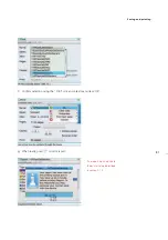
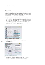
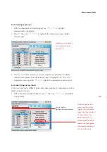
4. Press
e
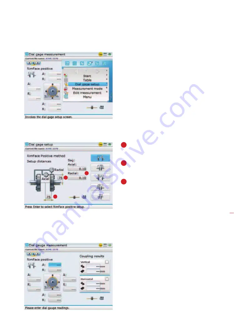
to confirm selection, then proceed to enter required axial and radial
dimensions, and sag values using the data entry keys .
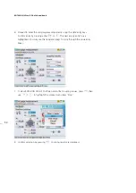
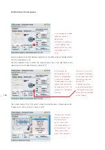
5. After entering the required dimensions and the
amount of bracket sag, press
ß
to return to the
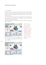
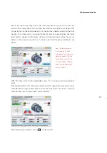
dial gauge measurement screen. To enter the dial gauge values, press
e
. The
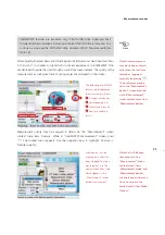
cursor highlights the 12:00 o’clock rim value box.
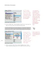
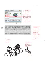
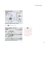
Alternatively, use the “Dial
gauge measurement”
screen context menu item
‘Start’ to begin entering the
dial gauge values.
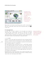
Measurement modes
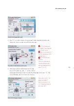
1
2
3
1
In this method, enter
the radius of the axial gauge
from the shaft center.
2
Here, we enter distance
from the radial gauge to the
coupling center.
3
Enter radial and axial
sag values.
Values are entered directly
using the data entry keys
and confirmed by pressing
either
e
or
ß
.
Summary of Contents for ROTALIGN Ultra iS
Page 1: ...ROTALIGN Ultra iS Operating handbook Shaft alignment...
Page 11: ...ROTALIGN Ultra iS Shaft handbook 10 This page intentionally left blank...
Page 56: ...55 Horizontal shaft alignment 1 2 4 5 6...
Page 123: ...ROTALIGN Ultra iS Shaft handbook 122 Page intentionally left blank...
Page 141: ...ROTALIGN Ultra iS Shaft handbook 140 This page intentionally left blank...
Page 177: ...ROTALIGN Ultra iS Shaft handbook 176 Page intentionally left blank...
Page 207: ...ROTALIGN Ultra iS Shaft handbook 206 Page intentionally left blank...
Page 213: ...ROTALIGN Ultra iS Shaft handbook 212 Declaration of conformity...

