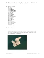
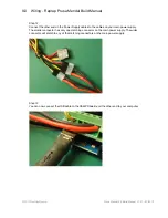
background image

8.0


Extruder & Hot End Assembly - Reprap Prusa Mendel Build Manual

©2012 NextDayReprap                                                                                        

Prusa Mendel Kit Build Manual  V1.01 - 07/2012
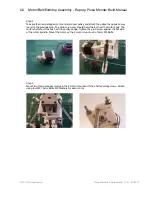
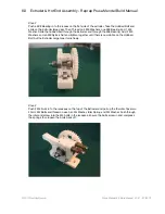
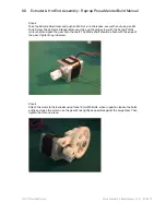
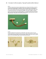
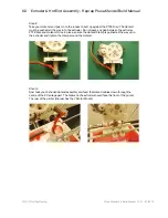
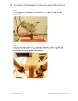
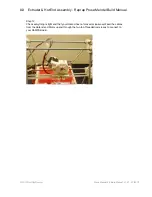
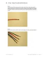
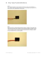
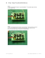
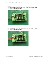
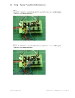
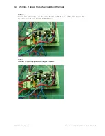
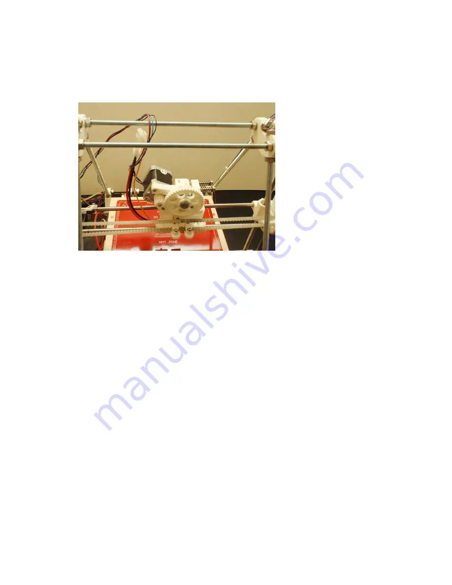
Step 13


Check everything is tight and that your Hotend has not moved or loosened. Feed the cables 
from the Hotend and Motor up and through the two top Threaded rods ready to connect to 
your RAMPS Board.

Summary of Contents for LM8UU

Page 1: ...e terms of the GNU General Public License as published by the Free Software Foundation either version 3 of the License or at your option any later version These programs are distributed in the hope that they will be useful but WITHOUT ANY WARRANTY without even the implied warranty of MERCHANTABILITY or FITNESS FOR A PARTICULAR PURPOSE See the GNU General Public License for more details You should ...

Page 2: ... firmly on a flat surface ensuring there is no force on fragile areas Then push the bearing into the recess increase the force until the bearing clips into place If you cannot get the bearing in place using a pair of large pliers and a small amount of force should ensure they go all the way in always ensure you keep the bearing level and avoid pushing in at an angle Plastic parts will wear over ti...

Page 3: ...ying Read all of the manual to enable you to make an informed decision Building and operating involves electricity so all necessary precautions should be taken and adhered to the printer runs on 12V supplied by a certified power supply so you shouldn t ever have to get involved with anything over 12V but bear in mind there can still be high currents involved and even at 12V they shouldn t be taken...

Page 4: ...equired 7 2 Assembly 8 0 Extruder Assembly 8 1 Parts Required 8 2 Assembly 3 3 Hot End Connection 9 0 Wiring 9 1 Parts Required 9 2 Completing Connections 9 3 RAMPS Diagram 9 4 RAMPS Board Connections 10 0 Computer setup 10 0 Hardware Driver Installation 10 1 Hardware Setup Connection 10 1 2 Ardunio Driver Windows XP Installation 10 1 3 Ardunio Driver Windows 7 Vista 10 2 Arduino Software Installa...

Page 5: ... Vista 10 7 0 Firmware Installation 10 7 1 Flashing Firmware Test Comms Windows XP 10 7 2 Flashing Firmware Test Comms Windows 7 Vista 10 8 Firmware Variables 11 0 Commissioning Calibration 11 1 Hardware Setup Connection 11 1 Frame Levelling 11 2 Bed Levelling 11 3 Endstops 11 4 Pololu Stepper Driver Calibration 11 5 Hot End 11 6 Heated Bed 11 7 Loading Filament 11 8 Removing Filament 11 9 Changin...

Page 6: ... printing except for a computer If anything is missing please advise us straight away Tools Ancillaries 0 1 Build Manual 0 2 Operation Manual 0 3 Software CD Flash Drive 0 4 33M 20mm Kapton Tape 0 5 Cable Ties 0 11 25 Kg White 3mm ABS Filament 0 12 Silver Tape 0 13 Cable Tidy 1 0 Electronics 1 1 Fully assembled RAMPS 1 4 Wired Soldered with Hot end power Thermistor attached 1 2 Ramps Power Cables ...

Page 7: ...4 550W ATX PSU 1 5 ATX Power Supply Adaptor to switch PSU 1 6 V2 Heat bed with Surface Mount LEDs Resistor Soldered Power Cable inc Thermistor 1 7 5 x Nema 17 Stepper Motors with Connectors Crimps 2012 NextDayReprap Prusa Mendel Kit Build Manual V1 01 07 2012 ...

Page 8: ...A2 Stainless 1 25mm Pitch Threaded Rod YUP 2 2 2x 450mm BZP 1 25mm Pitch Threaded Rod 2 3 1x 320mm BZP 1 25mm Pitch Threaded 2 4 6x 380mm BZP 1 25mm Pitch Threaded Rod 2 5 2x 330mm Bright Stainless Steel Round Rod YUP 2 6 2x 400mm Steel Round Rod 2 7 2x 400mm Steel Round Rod 2 8 1x 16mm Steel Round Rod Extruder Idler 2 9 1x 50mm Threaded Rod X Idler 2012 NextDayReprap Prusa Mendel Kit Build Manual...

Page 9: ...s 3 6 2x M4 45mm Hex Head Bolts 3 7 4x M4 40mm Countersunk Hex Socket Bolts 3 8 6x M8 30mm Fender Penny Washers 3 9 6x M2 Nuts 3 10 28x M3 Nuts 3 11 8x M4 Nuts 3 12 86x M8 Nuts 3 13 2x M3 Nylock Nuts 3 14 1x M8 Nylock Nuts 3 15 12x M2 Washers 3 16 56x M3 Washers 3 17 16x M4 Washers 3 18 88x M8 Washers 3 19 1x Hobbed Bolt 3 20 1x M3 10mm Grub Screw Extruder Small Gear 2012 NextDayReprap Prusa Mende...

Page 10: ...ngs Pulleys Couplings 4 1 12x LM8UU Bearings 1 Spare Some may have been pre fitted to the printed parts 4 2 9 x 608ZZ Bearings 1 Spare 4 3 2x 12 tooth T5 XL Aluminum Pulleys 4 4 2x Rigid Z Axis Couplings 2012 NextDayReprap Prusa Mendel Kit Build Manual V1 01 07 2012 ...

Page 11: ...prap Prusa Mendel Build Manual 5 0 Springs 5 1 4 x Heat Bed Springs 5 2 2x Z Axis Springs 5 3 2x Extruder Springs 6 0 Timing Belts 6 1 2x 1M Brecoflex 6mm T5 Belt 2012 NextDayReprap Prusa Mendel Kit Build Manual V1 01 07 2012 ...

Page 12: ...Mendel Build Manual 7 0 Build Plate 7 1 Laser Cut Aluminum Build Bed 7 2 Laser Cut Plywood Build Bed Top Plate 7 4 4x 51mm Bull Dog Clips 7 5 225cm x 225cm Build Plate Mirror 2012 NextDayReprap Prusa Mendel Kit Build Manual V1 01 07 2012 ...

Page 13: ...Reprap Prusa Mendel Build Manual 8 0 Printed Parts 8 1 4x Bar Clamps 8 2 2 x Rod Clamps 8 3 4 x Belt Clamps 8 4 3 x Endstop Holder 8 5 4 x LM8UU Bearing Pillows 2012 NextDayReprap Prusa Mendel Kit Build Manual V1 01 07 2012 ...

Page 14: ...a Mendel Build Manual 8 6 1 x Extruder 8 6 1 1 x Extruder Idler 8 6 2 1x Extruder Large Gear 8 6 3 1x Extruder Small Gear 8 7 2 x Frame Vertex 8 8 4x Frame Vertex with Foot 2012 NextDayReprap Prusa Mendel Kit Build Manual V1 01 07 2012 ...

Page 15: ...1 0 Bill of Materials Reprap Prusa Mendel Build Manual 8 9 2x Lower Z Mount 8 10 1 x X Motor Mount 8 11 1 x X Idler 8 12 1x Y Motor Mount 2012 NextDayReprap Prusa Mendel Kit Build Manual V1 01 07 2012 ...

Page 16: ...1 0 Bill of Materials Reprap Prusa Mendel Build Manual 8 13 2x Z Motor Mount 8 14 1 x X Carriage 8 15 1x Hot End Clamp 8 16 1x Ramps Box 2012 NextDayReprap Prusa Mendel Kit Build Manual V1 01 07 2012 ...

Page 17: ...1 0 Bill of Materials Reprap Prusa Mendel Build Manual All Printed Parts 2012 NextDayReprap Prusa Mendel Kit Build Manual V1 01 07 2012 ...

Page 18: ... Mount 2 x Frame Vertex 4 x Frame Vertex 4 x Bar Clamp 1 x Y Motor Mount 2 x Z Motor Mount 6 x 380mm Threaded Rod 4 x 300mm Threaded Rod 1 x 320mm Threaded Rod 2 x 450mm Threaded Rod 4 x M8 Fender Washers 80 x M8 Washers 78 x M8 Nuts 4 x 608 Bearings 2 2 Assembly Step 1 Take one Lower Z Mount and push in one 608 Bearing Push down against a solid flat surface to ensure the bearing sits flush in the...

Page 19: ...Mount M8 Washer M8 Nut M8 Nut M8 Washer Vertex with Foot M8 Washer M8 Nut Space the parts as in the photo below Leave approximately 5mm of thread showing on the end of the rods The Lower Z mount should be central on the rod Do not over tighten the M8 Nuts Leave them finger tight at this stage Step 3 Take one 380 mm Threaded Rod and thread on the following parts from left to right M8 Washer M8 Nut ...

Page 20: ...s from left to right M8 Nut M8 Washer M8 Nut Push this rod through the Frame Vertex from step 3 and attach an M8 washer and M8 nut to secure it Your component should look like the photo below Step 5 Take your component from step one and thread it on to the component from step four Add an M8 washer and M8 nut to the end of the threaded rods Your component should look like the photo below ...

Page 21: ...Make this gap 290 mm Loosely tighten the M8 nuts against the vertices and adjust evenly until all three sides are 290mm The Lower Z Mount should be left loose and approximately in the centre of the rod Check your measurements and tighten the M8 nuts against the vertices ensuring your frame side is stiff and even Step 7 Repeat steps 1 to 6 and you should now have two frame sides Place these to one ...

Page 22: ...r M8 Nut M8 Nut M8 Washer This component should look like the photo below Step 9 Take one 300mm threaded rod and thread on the following parts from left to right M8 Washer M8 Nut M8 Nut M8 Washer Bar Clamp M8 Washer M8 Nut M8 Nut Fender Washer M8 Washer 608 Bearing M8 Washer Fender Washer M8 Nut M8 Nut M8 Nut M8 Washer Bar Clamp M8 Washer M8 Nut M8 Nut M8 Washer This component should look like the...

Page 23: ...osest to the longer flat edge on the Y Motor Bracket from left to right M8 Washer M8 Nut M8 Nut M8 Washer Bar Clamp M8 Washer M8 Nut M8 Nut Fender Washer M8 Washer 608 Bearing M8 Washer Fender Washer M8 Nut M8 Washer Y Motor Bracket M8 Washer M8 Nut M8 Nut M8 Washer Bar Clamp M8 Washer M8 Nut M8 Nut M8 Washer Then Thread the following parts on the lower threaded rod from left to right M8 Washer M8...

Page 24: ...od and thread it with the following parts from left to right M8 Washer M8 Nut M8 Nut M8 Washer Space them as in the photo below Step 11 Take two 450 mm threaded rods and thread them each with the following parts from left to right M8 Washer M8 Nut M8 Nut M8 Washer Space them as in the photo below leave approximately 100mm of threaded rod on each end ...

Page 25: ...cure it Ensure the longer flat edge of the Y Motor Bracket is at the bottom Step 13 The next steps will take you through joining your two triangle components together using the rods created in steps 8 to 12 Take one of the frame sides you completed in step seven and the threaded rod from step from step 12 Slide the threaded rod through the lower Z mount and add an M8 Washer and M8 Nut to secure it...

Page 26: ...Manual V1 01 07 2012 Step 16 Take the rod from step nine and thread through the upper hole on the second vertex foot Use an M8 Washer and M8 Nut to secure it Step 15 Take the rod from step eight and thread through the lower hole on the second vertex foot Use an M8 Washer and M8 Nut to secure it ...

Page 27: ... step seven Push it onto each of the roads ensuring the lower Z mounts both face outwards with the 608 bearing upwards Secure the end of each of the threaded rods with an M8 Nut and M8 Washer Your frame should look like the picture below Step 17 Take a 450 mm Rod from step eleven and slide them through the upper frame vertices Use an M8 Washer and M8 Nut to secure it ...

Page 28: ...de then firmly tighten the plain side Once attached it should look like the picture below note that the clamp is loose Step 19 You can now adjust the width of the frame Gently tighten the frame until the gap between the inside edges of the vertices is 250mm Adjust each rod gradually tightening until all are 250mm gaps once tight your frame should be solid and sturdy on a level surface if you find ...

Page 29: ...se and then slide a 400mm Smooth Rod through from one side Before pushing the rod into the second rod clamp slide two LM8UU Bearings on to the rod Repeat this for both rods It should look like the picture below Step 2 Slide the rods into the second rod clamps Centre the rods 50mm from the inside edge of the frame vertices Do not fully tighten yet ensure the rod clamp has 1 2mm of play These will b...

Page 30: ...arings 8 x M3 Washer 8 x M3 20mm Bolt 8 x M3 Nut 1 x 50mm Threaded Rod 4 x M8 Nut 2 x M8 Fender Washer 5 x M8 Washer 4 2 Assembly Step 1 This step may already be completed and your X Mounts will have bearings installed and secured with cable ties If so go on to step two Take the X End Idler and push two LM8UU Bearings into the side recesses Push in until the bearings locate fully in the bearing gu...

Page 31: ...nd idler so that the spring is compressed inside the deep hexagonal recess on the part then thread an M8 Nut on from the opposite end and thread on until it meets the X end idler base Keep the spring compressed and twist the rod to locate the nut into the recess of the X End Idler Once the lower nut is located release the pressure on the spring and the rod should be held in place with the spring p...

Page 32: ... holes on the X end idler Then slide two LM8UU Bearings onto the rod closest to the motor mounting point Slide one LM8UU Bearing on to the other smooth rod Check the picture below to ensure your bearings are on the correct rods Step 5 Slide the X Motor Mount onto the rods and then slide two 300mm smooth rods through the LM8UU bearings in each X end part It should now look like the photo below ...

Page 33: ...axis and slide the threaded rods through the 608 bearings in the lower Z Mounts now slide the smooth rods on the XY axis up into the Z Motor mount clamps secure the top of the rods in the clamps by tightening the M8 nuts on the 450mm Threaded Rod top bars Step 7 Locate the bottom of the smooth rod in the cut out on the lower Z Mount Place an M3 Nut in each of the recesses on the lower Z mounts sec...

Page 34: ...to the X axis bearings and ensure the bearings are located correctly They should sit snug in the X carriage Use small zip ties to secure the carriage Step 9 Take the 50mm threaded rod and thread on two M8 Nuts and an M8 Washer Thread this though the hole on the X end idler Then thread on the following parts M8 Washer Fender Washer M8 Washer 608 Bearing M8 Washer Fender Washer M8 Nut M8 Nut Tighten...

Page 35: ...ed 4 x LM8UU Bearing Pillow 2 x Belt Clamp 8 x M3 10mm Bolt 4 x M3 20mm Bolt 12 x M3 Nut 16 x M3 Washer 5 2 Assembly Step 1 Take the four LM8UU bearing pillows and push M3 Nuts into each of the recesses Attach the bearing pillows to the aluminum bed using 10 mm M3 Bolts and M3 Washers On the opposite side of the aluminum bed attached two Belt Clamps using 20mm M3 Bolts and M3 Washers with M3 Nuts ...

Page 36: ...pillow If you feel unsure about how much pressure is required you may find is easier to remove the Y smooth rods and slide off the 4 LM8UU Bearings You can then install them in the pillows first Then slide the whole bed back on and put the Y rods back in place You can also loosen the M3 bolts holding the LM8UU Bearing Pillows to allow more adjustment Once the bed is in place go round and gradually...

Page 37: ... 3 x Microswitch 2 x Carbon Tube Insert 6 x M2 15mm Bolt 6 x M2 Nut 12 x M2 Washer 14 x M3 10mm 17 x M3 Washer 6 2 Assembly Step 1 Attach one aluminum pulley in to a Nema stepper motor ensuring the grub screw end is closest to the motor body the motor shaft should be flush with the pulleys edge Tighten the grub screw against the flat side of the motor spindle Mount the motor on to the Y motor moun...

Page 38: ...site way round to the previous step The grub screw end should be furtherest from the motor body The motor shaft should be flush with the pulleys edge Tighten the grub screw against the flat side of the motor spindle Mount the motor on the X motor mount using 10mm M3 Bolts Step 3 Mount two Nema stepper motors in the Z motor mounts with the shafts pointing down Attach using four M3 10mm Bolts M3 Was...

Page 39: ... couplings are in place they should support the X axis Now level the the X axis by measuring the height from your work surface to the bottom of once of the X End plastic parts Now hold the coupling still on that the side you measured and turn the coupling on the other side the X Mount should move up or down you can now adjust in the required direction until both X Mounts are the same height from y...

Page 40: ... move until the belt bearings and pulleys all run in a straight line gradually tighten the M8 Nuts the Belt Clamps and the Y motor Mount while sliding the bed back and forward and ensure the belt runs straight the bed should move smoothly however you may feel some resistance from the stepper motors Only a small amount of force should be needed to move the bed and it should not have a jerky motion ...

Page 41: ...he X Idler It should be positioned so the microswitch is depressed when the X Idler comes down the Z axis and hits the microswitch before hitting the print bed Loosely attach and this will be adjusted when the print bed is assembled Place the second of the Endstop assemblies on the X Axis smooth rod where is will be activated when the X Carriage returns along the X axis Place the third assembly on...

Page 42: ...Bolts 1 x Bed Thermistor 1 x Heated Bed 1 x Aluminum Tape 4 x M4 Nut 12 x M4 Washer 6 x Bulldog Clip 7 2 Assembly Step 1 Lay the Wooden Bed with the countersunk holes face down and the cut out at the bottom Using the Aluminum Tape attach the Bed Thermistor to the Wooden Bed The thermistor should poke through the central hole on the bed about 1mm Tape this securely and run the cable to the right ...

Page 43: ...d on an M4 Washer Bed Spring and M4 Washer thread through the Aluminum Bed and add an M4 Washer and M4 Nut Repeat this in each corner and then tighten down so that the springs compress to 2 3rds of the original length Measure the gap between the wooden bed and aluminium bed in one sprung corner and then adjust the other corners to the same height You can also use a small spirit level to ensure the...

Page 44: ... Bed on the Wooden bed thread the cables under the wooden bed and follow the thermistor cables out the left hand side Position the centre of the Heated Bed over the thermistor in the centre of the wooden bed and hold in place with the 6 bulldog clips Once in place remove the silver spring arms from the bulldog clips leaving the black clamps in place ...

Page 45: ...her 1 x M8 Nylock Nut 3 x 608 Bearing 1 x 16mm Smooth Rod 2 x M3 40mm Bolt 2 x M3 Nylock Nut 4 x M3 Washer 2 x M4 50mm Bolt 4 x M4 Nut 6 x M4 Washer 2 x Extruder Spring 1 x Nema Stepper Motor 1 x M3 Grub Screw 1 x M3 Nut 3 x M3 10mm Bolt 8 2 Assembly Step 1 Take the 16mm Smooth Rod and slide through a 608 Bearing Place this into the Extruder idler Push in until the Smooth Rod is fully located Usin...

Page 46: ... hobbed bolt through the Extruder and through the 608 Bearing Add 2 M8 Washers and an M8 Nylock Nut and tighten together until there is no wobble on the Hobbed Bolt but the Extruder Large Gear turns freely Step 3 Push 2 M4 Nuts in to the recesses on the top of the Extruder and pull up the the idler Take two 40mm M4 Bolts and thread on each an M4 Washer Idler Spring and M4 Washer Push through the i...

Page 47: ...ew Take a Nema Stepper Motor and Line up the grub screw with the flat part of the motor shaft and push the gear onto the shaft The Motor shaft should be flush with the edge of the gear Tighten the grub screw Step 5 Attach the motor to the Extruder using three 10mm M3 Bolts when in position loosen the bolts a little and push the motor in so the gears fit as tightly as possible against the Large Gea...

Page 48: ...ght this is to ensure the hot end stays in place You may find it useful to use a longer M3 bolt There will be one in the spare parts bag Leave the clamp loose Push two 50mm Hex Top Bolts through the base of the extruder so the heads locate in the recesses Slide the Hot end clamp on to the Hex Top Bolts Ensure that the clamp opening is on the same side as the extruder gear The clamp only fits on to...

Page 49: ...t is protruding from the block or has slipped out completely use a pair of tweezers and gently push it in to the aluminum block Hold the Brass tip up to a light and look through the Hotend Make sure you can see the pin hole and ensure there is no debris inside Make sure the PTFE lining is pushed in fully and flush with the top of the Hotend Step 8 Take your Hotend Part and remove the white PTFE Di...

Page 50: ... way in to the extruder Do not leave any gap between the extruder PTFE Disc and Hotend Once in place ensure the Hotend Clamp is pushed all the way up to the extruder and tighten the clamp around the Hotend Step 10 Now take your Extruder Hotend assembly and feed the Hotend cables down through the centre of the X Carriage part The Gears on the extruder should face the front of the printer The rear o...

Page 51: ...the Hotend Clamp down on the the X Carriage and it should clip tightly in to place Use an M4 Washer and M4 Nut on each of the hex bolts and tighten all the way up Make sure the Extruder assembly is tightly held and does not wobble Step 11 Once the cables are through line up the Hex Bots with the X Carriage and guide the whole assembly down ...

Page 52: ... 2012 NextDayReprap Prusa Mendel Kit Build Manual V1 01 07 2012 Step 13 Check everything is tight and that your Hotend has not moved or loosened Feed the cables from the Hotend and Motor up and through the two top Threaded rods ready to connect to your RAMPS Board ...

Page 53: ...connected to the wires before you can attach them to your RAMPS hardware The following instructions will guide you through the process If you are experienced at this type of connection we recommend that you put small amount of solder on the crimps to ensure there longevity You should always double check the order the the wires are connected before pushing in to the black plastic PC Header plugs as...

Page 54: ...connectors and place the Red stripped wire as shown below Ensure the longer metal prongs on the connector line up with the sheathed part of the wire The bare wire should sit in the centre of the connector Step 3 Now crimp down the smaller metal prongs Ensure they hold the wire tight Make sure there are no loose or frayed strands of wire ...

Page 55: ...e grip the sheathed wires but do not crush the wire Ensure your crimps are small and tight on the wire Ensure the connector is not bent The whole of the metal connector will slide in to the plastic PC Header connector so you should ensure there are no wires hanging and the metal crimp is secure Step 5 Repeat the the process until all four wires from the stepper motor have connectors attached ...

Page 56: ...e red wire goes in to the right hand hole in the connector Step 7 Slide the connector in to the PC Header connector as shown in the photo The connector must slide all the way in until your feel a click as the crimp connector locates in to the plastic If your crimp will not go all the way in check that your crimped prongs are tight enough To check that your wire is all the way in look in to the PC ...

Page 57: ... 01 07 2012 Step 8 Repeat fitting the connectors in the PC Header connector for each wire Ensure the order matches the photo below From left to right it should be Black Green Blue and Red Step 9 Repeat the steps for all five of your stepper motors You are now ready to connect to your RAMPS Board ...

Page 58: ...9 0 Wiring Reprap Prusa Mendel Build Manual 2012 NextDayReprap Prusa Mendel Kit Build Manual V1 01 07 2012 9 3 RAMPS Board Diagram ...

Page 59: ...o your Hotend As you connect your components to the ramps board use cable ties to hold the cables against the frame and ensure no cables are trapped or touching moving parts We recommend loosely tidying cables until your printer is fully running and then making permanent later Make sure when connecting plastic connectors that the pins are fully inserted in to the plastic plugs but have not pushed ...

Page 60: ...switch to the connector labelled x There should be two rows of 6 pins The x is the first pair the next endstop connectors will use every other pair of pins Ensure the black cable is closest to the centre of the RAMPS board Step 2 Connect the Heated Bed Thermistor to connector labelled T1 The orientation does not matter on this connector only ...

Page 61: ...nual V1 01 07 2012 Step 5 Connect the Z Endstop Microswitch to the connector labelled z Ensure the black cable is closest to the centre of the RAMPS board Step 4 Connect the Y Endstop Microswitch to the connector labelled y Ensure the black cable is closest to the centre of the RAMPS board ...

Page 62: ...anual V1 01 07 2012 Step 7 Connect the Y Motor to the connector labelled Z Ensure the Red cable is closest to the green screw terminals on the RAMPS board Step 6 Connect the X Motor to the connector labelled X Ensure the Red cable is closest to the green screw terminals on the RAMPS board ...

Page 63: ...7 2012 Step 9 Connect the second Z Motor to the upper connector labelled Z Ensure the Red cable is closest to the green screw terminals on the RAMPS board Step 8 Connect the first Z Motor to the lower connector labelled Z Ensure the Red cable is closest to the green screw terminals on the RAMPS board ...

Page 64: ...tDayReprap Prusa Mendel Kit Build Manual V1 01 07 2012 Step 11 Connect Power Supply cable to the green socket Step 10 Connect the Extruder Motor to the connector labelled E0 Ensure the Red cable is closest to the green screw terminals on the RAMPS board ...

Page 65: ... the USB cable to the RAMPS board and the other end to your computer Step 12 Connect the other end on the Power Supply cables to the cables on your main power supply The smaller connector has only one matching connector on the main power supply The wider connector will atatch to any of the matching connectors on the main power supply ...

Page 66: ...MPS Board Step 2 Now switch the power switch on the back of the ATX Power Supply 1 4 to the on position The fan on the Power Supply should start to spin 10 0 Computer Setup Reprap Prusa Mendel Build Manual 2012 NextDayReprap Prusa Mendel Kit Build Manual V1 01 07 2012 10 1 Connecting Hardware Driver Installation 10 1 1 Hardware Setup Connection Ensure your computer is in good working order and you...

Page 67: ...and Select Next Step 1 A Found New Hardware Wizard Dialogue window should appear Select No not this time and select Next 10 1 Connecting Hardware Driver Installation 10 1 2 Ardunio Driver Windows XP Installation 10 0 Computer Setup Reprap Prusa Mendel Build Manual 2012 NextDayReprap Prusa Mendel Kit Build Manual V1 01 07 2012 ...

Page 68: ...tep 4 Select Ports COM LPT and Select Next Step 5 Select Have Disk Step 6 Select Browse 10 0 Computer Setup Reprap Prusa Mendel Build Manual 2012 NextDayReprap Prusa Mendel Kit Build Manual V1 01 07 2012 ...

Page 69: ...and then into Drivers Step 8 Select Ardunio MEGA 2560 REV3 inf and select Open Step 9 Select Ardunio MEGA 2560 R3 and select Next 10 0 Computer Setup Reprap Prusa Mendel Build Manual 2012 NextDayReprap Prusa Mendel Kit Build Manual V1 01 07 2012 ...

Page 70: ...ith your computer you should see the following message pop up after selecting Finish Now proceed to 1 11 Setting Port Speed Step 10 Select Continue Anyway 10 0 Computer Setup Reprap Prusa Mendel Build Manual 2012 NextDayReprap Prusa Mendel Kit Build Manual V1 01 07 2012 ...

Page 71: ... just created by installing the Arduino driver in the previous section Step 1 Navigate to the Windows Control Panel and select system and select the hardware tab Step 2 Navigate to Ports COM LPT and expand it by selecting the symbol now select Arduino MEGA 2560 R3 and right click and select Properties 10 0 Computer Setup Reprap Prusa Mendel Build Manual 2012 NextDayReprap Prusa Mendel Kit Build Ma...

Page 72: ...re setting up the printing software in brackets after the device title Then Select the Port Settings Tab Step 4 Select Bits per second Step 5 Select the 115200 from the drop down menu 10 0 Computer Setup Reprap Prusa Mendel Build Manual 2012 NextDayReprap Prusa Mendel Kit Build Manual V1 01 07 2012 ...

Page 73: ...Control Panel and Select System and then select Device Manager on the top left hand side You should then be able to see an unknown device under other devices Step 3 Right click over the unknown device and select properties 10 1 Connecting Hardware Driver Installation 10 1 3 Ardunio Driver Windows 7 Vista 10 0 Computer Setup Reprap Prusa Mendel Build Manual 2012 NextDayReprap Prusa Mendel Kit Build...

Page 74: ...elect Update Driver Step 5 Select Browse my computer for driver software Step 6 Select Browse 10 0 Computer Setup Reprap Prusa Mendel Build Manual 2012 NextDayReprap Prusa Mendel Kit Build Manual V1 01 07 2012 ...

Page 75: ...Step 7 Select Ports COM LPT Step 8 Select Have Disk Step 9 Select Browse 10 0 Computer Setup Reprap Prusa Mendel Build Manual 2012 NextDayReprap Prusa Mendel Kit Build Manual V1 01 07 2012 ...

Page 76: ... into the drivers folder and then select Arduino MEGA 2560 REV3 inf and click Open Step 11 Select Ok Step 12 Select Arduino Mega 2560 R3 then select Next 10 0 Computer Setup Reprap Prusa Mendel Build Manual 2012 NextDayReprap Prusa Mendel Kit Build Manual V1 01 07 2012 ...

Page 77: ...14 After a short while it could be up to a few minutes depending on your computer speed the following message should appear then select Close 10 0 Computer Setup Reprap Prusa Mendel Build Manual 2012 NextDayReprap Prusa Mendel Kit Build Manual V1 01 07 2012 ...

Page 78: ...the Arduino driver in the previous section Step 1 Navigate to the Windows Control Panel and select System and then select device manager from the top left hand side Step 2 Navigate to Ports COM LPT and expand by selecting the triangle arrow to the left of it then right click over Arduino Mega 2560 R3 COM and select Properties 10 0 Computer Setup Reprap Prusa Mendel Build Manual 2012 NextDayReprap ...

Page 79: ...this later when setting up your printer software Now select Port Settings Step 4 Select the Bits per second drop down menu and select 115200 then select Ok Step 5 Select Ok now we have set the port speed we 10 0 Computer Setup Reprap Prusa Mendel Build Manual 2012 NextDayReprap Prusa Mendel Kit Build Manual V1 01 07 2012 ...

Page 80: ...to Desktop create shortcut this will make things easier later on Install application Insert the software CD that came with your Kit or navigate to http arduino cc hu Main Software then either Download Ver 0 22 MUST BE THIS VERSION of the Ardunio Dev Environment or copy it from the CD take the Folder called ARDUINO 022 and place inside the newly created REPRAP folder Make sure that when you downloa...

Page 81: ...2 7 we need to install PYSerial for Python Navigate to the PYSerial folder and select pyserial 2 5 win32 exe or download from http pypi python org packages any p pyserial pyserial 2 5 win32 exe 10 3 Python Environment Dependencies Installation 10 3 1 Python Environment Dependencies Windows XP Installation 10 0 Computer Setup Reprap Prusa Mendel Build Manual 2012 NextDayReprap Prusa Mendel Kit Buil...

Page 82: ...load here http downloads sourceforge net wxpython wxPython2 8 win32 unicode 2 8 12 0 py27 exe Step 6 Select Next and follow the instructions to install Python 8 support On the final dialogue installation complete screen un tick convert py files to pyc and select Finish 10 0 Computer Setup Reprap Prusa Mendel Build Manual 2012 NextDayReprap Prusa Mendel Kit Build Manual V1 01 07 2012 ...

Page 83: ...follow the instructions to complete the installation of pyreadline 1 7 Step 9 Now we need to install PYGLET First navigate to your reprap folder and check that you have a folder called pyglet 1 1 4 Alternatively download here http pyglet googlecode com files pyglet 1 1 4 zip 10 0 Computer Setup Reprap Prusa Mendel Build Manual 2012 NextDayReprap Prusa Mendel Kit Build Manual V1 01 07 2012 ...

Page 84: ...T cd pyglet 1 1 4 Now you should be in the pyglet 1 1 4 folder now type setup py install and press return Step 12 You should now see some text passing the screen which should complete the installation of Pyglet once this is comeplete type exit and press return 10 0 Computer Setup Reprap Prusa Mendel Build Manual 2012 NextDayReprap Prusa Mendel Kit Build Manual V1 01 07 2012 ...

Page 85: ...thon Environment Dependencies Windows 7 Vista Step 1 Navigate to The Python 2 7 2 folder and then select python 2 7 2 msi or download from http python org ftp python 2 7 2 python 2 7 2 msi 10 0 Computer Setup Reprap Prusa Mendel Build Manual 2012 NextDayReprap Prusa Mendel Kit Build Manual V1 01 07 2012 ...

Page 86: ...ial 2 5 win32 exe Step 4 Select Next and complete the installation of PY Serial Step 5 Install Python 8 support Navigate to Python 8 folder and select wxPython2 8 win32 unicode 2 8 12 0 py27 exe or download here http downloads sourceforge net wxpython wxPython2 8 win32 unicode 2 8 12 0 py27 exe 10 0 Computer Setup Reprap Prusa Mendel Build Manual 2012 NextDayReprap Prusa Mendel Kit Build Manual V1...

Page 87: ... installation complete screen un tick convert py files to pyc and select Finish Step 7 Navigate to the PYREADLINE Folder and select pyreadline 1 7 win32 exe or download here http launchpad net pyreadline 1 7 1 7 download pyreadline 1 7 win32 exe Step 8 Select Next and follow the instructions to complete the installation of pyreadline 1 7 10 0 Computer Setup Reprap Prusa Mendel Build Manual 2012 Ne...

Page 88: ...4 zip Step 10 Select Start and then select Run and type cmd Step 11 At the command prompt navigate to the pyglet 1 1 4 folder from your home directory cd desktop cd REPRAP cd PYGLET cd pyglet 1 1 4 Now you should be in the pyglet 1 1 4 folder now type setup py install and press return 10 0 Computer Setup Reprap Prusa Mendel Build Manual 2012 NextDayReprap Prusa Mendel Kit Build Manual V1 01 07 201...

Page 89: ...of Pyglet once this is comeplete type exit and press return You have now completed the Python and Dependencies installation please proceed to 10 4 Pronterface Printrun Installation 10 0 Computer Setup Reprap Prusa Mendel Build Manual 2012 NextDayReprap Prusa Mendel Kit Build Manual V1 01 07 2012 ...

Page 90: ...lder Step 2 Navigate inside the kilment Printrun 65e0121 folder and right click on pronterface py and select send to desktop create shortcut Step 3 Now you should have a shortcut on your desktop called shortcut to pronterface py double click on this and Pronterface Printrun should open You have successfully setup Pronterface PrintRun 10 0 Computer Setup Reprap Prusa Mendel Build Manual 2012 NextDa...

Page 91: ... inside the Reprap folder Navigate to pronteface py and right click on it and select Send to and then desktop Create Shortcut Step 2 Now you should have a shortcut on your desktop called shortcut to pronterface py double click on this and Pronterface Printrun should open You have successfully setup Pronterface PrintRun 10 0 Computer Setup Reprap Prusa Mendel Build Manual 2012 NextDayReprap Prusa M...

Page 92: ...s folders drives Now right click on the folder and select copy Step 2 Now navigate to the root of your home folder Documents Settings Your User Name and then paste the skeinforge folder into the root of your home directory Skeinforge is now installed in the correct place for Printrun Pronterface to use your skeinforge profiles will be stored in this folder 10 0 Computer Setup Reprap Prusa Mendel B...

Page 93: ...s folders drives Now right click on the folder and select copy Step 2 Now navigate to the root of your home folder C Drive Main Drive Users Your User Name and then paste the skeinforge folder into the root of your home directory Skeinforge is now installed in the correct place for Printrun Pronterface to use your skeinforge profiles will be stored in this folder 10 0 Computer Setup Reprap Prusa Me...

Page 94: ... desktop You should have also made a note of your COM Port Number during the Arduino Driver Installation 10 1 1 and have set the Port Speed to 115200 within the windows control panel 10 1 2 Your Ramps Board should be powered on and connected to the computer by USB 10 1 1 Step 1 Select the Pronterface py shortcut on your desktop and pronterface should load Step 2 Now Select the correct Com Port fro...

Page 95: ... is the speed at which the extruder will operate when pressing the manual extrude and reverse buttons Step 5 Now Select connect from the top menu and after a short pause connecting Printer is now Online should appear in the dialogue menu You have now successfully connected to the printer so now we need to check the communication between the software the printer 10 0 Computer Setup Reprap Prusa Men...

Page 96: ...towards home the endstop end of the X Axis until it reaches the endstop and the endstop should click and X Axis will stop moving NOTE if the endstop fails and x axis tries to keep moving select the reset button along the top menu bar and the printer should stop trying to move n b you ll need to click on connect again after you have selected reset Step 8 Now repeat the process for the Y Axis build ...

Page 97: ... until you hit the endstop and it stops If necessary adjust the endstop height position on the vertical smooth rod of the Z axis to ensure the endstop is hit before the hot end hits the bed Step 10 Now select the Heater Temperature and select 230 Abs from the drop down this is the temperature to which the hot end will be heated and maintained and then select the Set button a red light will appear ...

Page 98: ...u should now see the hot end and the bed temperature respectively these will be updated every few seconds and you should see them going up until they reach their respective set level and then the software will maintain them near to their set temperatures Step 13 Now select settings from the top menu and select Slicing Settings and Select the Profile Type and select Extrusion 10 0 Computer Setup Re...

Page 99: ...lect save all at the bottom of the window Step 15 Now we have set the software up and it s connected to the printer and communicating we need to move onto section 11 00 Commissioning 10 0 Computer Setup Reprap Prusa Mendel Build Manual 2012 NextDayReprap Prusa Mendel Kit Build Manual V1 01 07 2012 ...

Page 100: ...ur desktop You should have also made a note of your COM Port Number during the Arduino Driver Installation 10 2 1 and have set the Port Speed to 115200 within the windows control panel 10 2 2 Your Ramps Board should be powered on and connected to the computer by USB 10 2 1 Step 1 Select the Pronterface py shortcut on your desktop and pronterface should load Step 2 Now Select the correct Com Port f...

Page 101: ...ld appear in the dialogue menu You have now successfully connected to the printer so now we need to check the communication between the software the printer Step 4 Now Select settings from the top menu and select Options then set the e_federate value to 115 this is the speed at which the extruder will operate when pressing the manual extrude and reverse buttons 10 0 Computer Setup Reprap Prusa Men...

Page 102: ...ection towards home the endstop end of the X Axis until it reaches the endstop and the endstop should click and X Axis will stop moving NOTE if the endstop fails and x axis tries to keep moving select the reset button along the top menu bar and the printer should stop trying to move n b you ll need to click on connect again after you have selected reset Step 8 Now repeat the process for the Y Axis...

Page 103: ... until you hit the endstop and it stops If necessary adjust the endstop height position on the vertical smooth rod of the Z axis to ensure the endstop is hit before the hot end hits the bed Step 10 Now select the Heater Temperature and select 230 Abs from the drop down this is the temperature to which the hot end will be heated and maintained and then select the Set button a red light will appear ...

Page 104: ...Settings and Select the Profile Type and select Extrusion Step 12 Now select the tick box at the top monitor printer and you should now see the hot end and the bed temperature respectively these will be updated every few seconds and you should see them going up until they reach their respective set level and then the software will maintain them near to their set temperatures 10 0 Computer Setup Re...

Page 105: ...lect save all at the bottom of the window Step 15 Now we have set the software up and it s connected to the printer and communicating we need to move onto section 11 00 Commissioning 10 0 Computer Setup Reprap Prusa Mendel Build Manual 2012 NextDayReprap Prusa Mendel Kit Build Manual V1 01 07 2012 ...

Page 106: ...some h files and a file called sprinter pde this is your firmware file that needs to be opened within the Arduino development This will then allow you to modify the settings within the firmware and upload it to the chip on the RAMPS board Note you can t actually view the firmware that is on the chip or rip the firmware from the chip so it is probably prudent to make a backup copy of our sprinter f...

Page 107: ... and set this to Arduino Mega 2560 Step 3 Select File Open and navigate to your SPRINTER folder and select the file Sprinter pde and select Open 10 0 Computer Setup Reprap Prusa Mendel Build Manual 2012 NextDayReprap Prusa Mendel Kit Build Manual V1 01 07 2012 ...

Page 108: ...is tab to modify the firmware Step 5 Now we can select the configuration h file and here we can make modifications to the firmware variables such as setting the main board type thermistor types steps per mm etc Please refer to section 11 7 4 Firmware variables for guidance on what the values within this file mean and calculating them 10 0 Computer Setup Reprap Prusa Mendel Build Manual 2012 NextDa...

Page 109: ... from the icon buttons across the top and then you should see a message at the bottom of the screen saying Uploading to I O Board Step 7 The status box at the bottom of the window should then display Binary sketch size bytes of a bytes maximum 10 0 Computer Setup Reprap Prusa Mendel Build Manual 2012 NextDayReprap Prusa Mendel Kit Build Manual V1 01 07 2012 ...

Page 110: ...Board You should now save your modifications by selecting the button icon on the far right or selecting File Save For help on the actual firmware variables there meaning and calculating their values please read section 10 7 4 Firmware Variables 10 0 Computer Setup Reprap Prusa Mendel Build Manual 2012 NextDayReprap Prusa Mendel Kit Build Manual V1 01 07 2012 ...

Page 111: ...ee some h files and a file called sprinter pde this is your firmware file that needs to be opened within the Arduino development This will then allow you to modify the settings within the firmware and upload it to the chip on the RAMPS board Note you can t actually view the firmware that is on the chip or rip the firmware from the chip so it is probably prudent to make a backup copy of our sprinte...

Page 112: ...Open Step 4 A new window should now open with various tabs across the top below the main menu The 1st tab should read Sprinter and the second tab should read configuration h this is the tab we need to select and then we can adjust the variables within this tab to modify the firmware 10 0 Computer Setup Reprap Prusa Mendel Build Manual 2012 NextDayReprap Prusa Mendel Kit Build Manual V1 01 07 2012 ...

Page 113: ... 6 Once modifications have been made to the configuration h file then it can be uploaded to the RAMPS Board to do this select the right arrow icon button from the icon buttons across the top and then you should see a message at the bottom of the screen saying Uploading to I O Board Step 7 The status box at the bottom of the window should then display Binary sketch size bytes of a bytes maximum 10 ...

Page 114: ...Board You should now save your modifications by selecting the button icon on the far right or selecting File Save For help on the actual firmware variables there meaning and calculating their values please read section 10 7 4 Firmware Variables 10 0 Computer Setup Reprap Prusa Mendel Build Manual 2012 NextDayReprap Prusa Mendel Kit Build Manual V1 01 07 2012 ...

Page 115: ...hic Electronics Our Kit Value We use RAMPS 1 4 so our value is define MOTHERBOARD 33 We use the Arduino Development environment to view and edit the the firmware please refer to section 10 7 1 XP or 10 7 2 Vista Win7 for instructions for using the development environment define THERMISTORHEATER define THERMISTORBED These values tell the chip which kind of thermistors are being used for the Hot End...

Page 116: ...e value we use for X and Y axis Calculate Z Axis value To Calculate the the Z axis value we use a fraction steps for a 360 rotation of stepper Threaded Rod Pitch as our our Motors have a 1 8 step angle and the Pololu A4988 Stepper Drivers use 1 16 stepping this results in 3200 360 1 8 200 then multiply by 16 results in 3200 The pitch of our Z Axis Rod is 1 25 so the value for our Z axis is 3200 1 ...

Page 117: ...be able to get this value const bool ENDSTOPS_INVERTING true This value defines the behavior of the endstops setting the value to true inverts the the logic of the endstops define BAUDRATE 115200 This value determines the the baud rate speed of the serial port that printer is connected to This should be the same value as set in port settings in 10 1 2 10 1 3 and should be reflected in within Pront...

Page 118: ...ool max_software_endstops true If this value is set to true the axes won t move to coordinates greater than the defined lengths below const int X_MAX_LENGTH 200 const int Y_MAX_LENGTH 200 const int Z_MAX_LENGTH 135 These values determine the maximum build area i e the maximum length away from home that can be travelled on the respective axis 10 0 Computer Setup Reprap Prusa Mendel Build Manual 201...

Page 119: ...ommend you read through both the computer set up sections and commissioning sections before starting either These sections include instructions for setting up important parts of your printer and both should be carried out at the same time Step 1 Check that the surface your printer will be used on is level Position your printer where is will be used Remember to allow enough room for the bed to move...

Page 120: ...he lower Z axis and move the axis until your Z Axis is level then tighten Repeat this for both of the Z Axis Step 3 Now measure then gap between your work surface and the base of the X End Motor Mount Make a note of this and then hold the coupling tight on that Z Axis Twist the opposing Z Axis coupling to raise or lower your X Idler Mount until it is the same height as the other X end If you have ...

Page 121: ... of your bed have the springs securely in place Measure the height from your work surface to the wooden bed in one corner Adjust the corner screws until all four corners are the same height 11 2 Bed Leveling Step 2 If you have a spirit level you can use it to ensure your bed is perfectly level Place it on each edge of the bed and adjust the bed screws to level ...

Page 122: ...ne of our mirror beds or another glass layer we recommend you use bulldog clips to clamp the mirror and heated bed down and then check the level of the bed Step 4 Now bring your Z axis down until the tip of the Hotend is approximately 10mm from the bed If you have set up your computer you can use the software to lower the Axis Be careful not to go too far as you risk damaging the Hotend nib agains...

Page 123: ...e if the gaps between your bed and the Hotend stays consitent If you see that the gap changes adjust the bed corners to bring it level Do the same with the X Axis Move the X Carriage side to side and watch the Hotend tip Adjust the X Axis by truning the Z Axis couplings while holding the other still This will raise or lower the end Step 6 Repeat these steps while gradually lowering the X Axis down...

Page 124: ...Axis end stop Can be pushed up against the base of the X end so that the pin is depressed Your Hotend should be close to the right height following the previous steps Now using the software raise your Z axis up by 10 20 mm Then lower your Z Axis by the smallest increments position the end stop so the switch is pressed before the Hotend nib touches the bed surface The correct gap between bed and ni...

Page 125: ...b is above the bed still and if it has gane past or will catch on your bulldog clips then bring the Endstop in along the rod to adjust Step 3 Ensure the Y Endstop is in position to be activeated by the Aluminum bed when it returns alongs its axis Check that your bulldog clips and cables do not catch on it Step 4 With your Endstops in place and your frame and bed level ensure your computer software...

Page 126: ...ich can take a maximum current of 1 68A at a 2 8V the Polulo A4988 Stepper Driver can drive up to 2A this is far higher than the level required resulting in the stepper motors running a lot cooler There is a very fine line between too much current and too little current in relation to the accurate operation of the stepper motor itself The best starting point is about 0 7x the rated current this is...

Page 127: ...the current by putting the ground probe on the 2nd pin from the left on the top row and the positive probe on the adjustment pot poke the probe into the pot until you get a reading on your multimeter Make sure you don t slip and touch any of the other pins as this could damage the stepper driver 11 0 Commissioning Calibration Reprap Prusa Mendel Build Manual 2012 NextDayReprap Prusa Mendel Kit Bui...

Page 128: ...y powerful for the printer and after a certain point the motor won t move again and will vibrate and get very hot Depending upon which motors are being used more heavily when printing will depict how warm hot they get along with their respective heat sinks on the stepper drivers so for example the Extruder stepper may well be considerably hotter than the z axis stepper motor as it is Step 3 Now we...

Page 129: ...check box at the top in Pronterface labelled Monitor Printer will start Pronterface regular temperature checks and the latest temperature for Hotend and Bed will be displayed 11 5 Hotend You can now turn on the heated bed In the Pronterface software check your bed temp is 110 in the dialog box and click Set The Bed is much slower to heat than the Hotend Also any further layers on your heated bed w...

Page 130: ...e 230 for ABS Ensure your motors are set to off in the Pronterface software Remove the two sprung bolts from the Extruder Idler and pull the Idler down 11 7 Loading Filament Step 2 Take the end of your filament and ensure is has no kinks or twists in it Take the end of your filament and using wire cutters or a stanley knife cut diagonally across the filament This creates a pointed end to ease feed...

Page 131: ...bed bolt the filament will be pushed away from the lower hole Use small pliers to push the filament down throught the lower hole Once in turn the large gear on the extruder to feed the filament through Step 4 Keep feeding the filament until it reaches the bottom of the Hotend you should see the filament start to ooze from the Hotend Keep your fingers loosely gripped on the filament as it s being s...

Page 132: ...roximately 50mm from the bed In Pronterface check that the Extrude length is 5mm and click Extrude You should see filament come out of your Hotend Now increase the extrude length in pronterface to 50mm and click extrude Watch the filament as is releases You should see a consistent line extruded at a consistent speed If your filament is extruding fast then slow or it is coming out at different thic...

Page 133: ...ff the motors in the Pronterface software Button Located on the top left hand side Then remove the two Sprung bolts in the extruder idler 11 8 Removing Filament Step 2 Grip the filament above the extruder and pull up in one swift movement This ensures the filament comes out cleanly and no blobs of plastic are left behind You may find it helpful to turn the large gear on the extruder in reverse as ...

Page 134: ...ndel Kit Build Manual V1 01 07 2012 Step 3 Whenever removing filament always check your Hotend is fully located in the extruder recess before reloading If necessary you can loosen the Hotend clamp an holding the Hotend with pliers or grips push up into position and retighten the Hotend Clamp ...

Page 135: ...en changing a hot end always check that the PTFE disc stays in place in the extruder recess Always check for debris in the extruder and hotend If your hotend will remain out of your printer for some time place a strip of kapton tape over the hole and ensure the brass nib does not get damaged Refit or install your replacement by sliding through the hotend clamp and in to the extruder recess Ensure ...

Page 136: ...ome Gcode from an STL 3D Design file The Gcode is the list of commands that is directly transmitted to the printer In order to generate the G Code we need to use the compose function of Pronterface this creates a graphical representation of your print bed allows you to position the object on the heat bed and then pronterface generates the Gcode by using Skeinforge Pronterface acts as a front end f...

Page 137: ...to generate the G Code On a relatively modern dual core machine it should take less than a minute or so to generate the code for the test cube the log will indicate once it s complete and an image should appear in the central window The Gcode that is generated is stored in a folder called Temp STL inside the Printrun Pronterface application folder If you want to keep the gcode you generated to sav...

Page 138: ...down against your bed by the hotend nib your Z axis endstop may be too low and you risk damaging the bed This is when having your power supply main switch close can help avoid accidentally scraping the hotend nib on the bed If your hotend does scrape your bed or hit a bulldog clip you should always check and reseat the hotend Watch as your printer builds the first layer If the lines judder check y...

Page 139: ...tarting your print When the cube is complete the hotend will move away The bed and hotend will turn off and begin to cool You should allow the print to cool before removing from the bed Be careful not to damage the heated bed when removing prints Move your hotend to its home position and set the heated bed and hotend temperature and you are ready to print again 11 0 Commissioning Calibration Repra...

Page 140: ...to enable you to make an informed decision Building and operating involves electricity so all necessary precautions should be taken and adhered to the printer runs on 12V supplied by a certified power supply so you shouldn t ever have to get involved with anything over 12V but bear in mind there can still be high currents involved and even at 12V they shouldn t be taken lightly High temperatures a...

Page 141: ...ected or dislodged that goes un noticed prior to commencing a print Endstops Make sure they haven t moved on their respective axis and that they are connected electrically Axis Make sure they are tightly gripped and don t have any vertical or horizontal movement When sending manual commands to the printer from the Pronterface software always pay attention to what the printer is actually doing and ...

Page 142: ...hers across the printer to ensure they are still tight and haven t worked loose as the printer move s and vibrates a lot it is prudent to check these regularly It is important they don t work loose as it can affect the geometry and stability of the 3D Printer 12 3 Nuts Bolts The Extruder is one of the hardest working parts of the printer Every so often open the extruder Idler and clean out any loo...

Page 143: ...ions and tighten them if they have become loose or looser 12 5 Electronics 12 7 Build Surface Make sure you keep your build surface clean dry and free of oil grease In order for ABS Plastic to adhere to the build surface and to prevent warping you will be using kapton tape on your build surface The kapton tape will need to be replaced and re applied to the build plate when it gets damaged scratche...

Page 144: ...ed in an erroneous fashion For example you move the y axis 100mm away from home by pressing the button in the pronterface software but there is only 60mm left of free axis so when the instruction is sent the printer keeps trying to move the Y Axis for another 40mm after it has hit the end this could result in the bearings nudging within their mounting pillows This would then cause the bed level to...

Reviews: