10. Fitting the Pi Case to the Frame
Required:
1 M3 14mm screw
2 M3 nuts
Pi Base with PSU
Optional GPIO Cable
3 M3 30mm screws
200mm cable sleeving
Power Supply Cable Installation
1. Measure the power cable, and cut such that there is a total of 500mm of cable
from the power converter module to the end (including the in-line fuse if fitted).
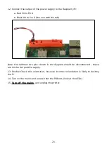
2. Thread the power cable through the Pi Case hole and through the cable sleeving.
3. Fit a Xmm (blue) spade crimp connector to each of the cable ends.
GPIO Cable Installation
1. Build or use a 600mm (minimum) long 2.54mm ribbon cable or male to female
patch cable.
Hint: If you have 2-way or 1-way connectors fitted, they will pass through the hole
in the Pi Case.
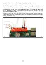
2. Thread the connectors through the case and down the cable sleeving alongside
the power cable, leaving an 80mm ‘flying lead’ within the case.
Pi Connector Installation
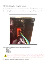
1. Check that the Pi you will be using has the expansion header fitted.
2. If you wish to have a hard reset switch, check the Pi you will be using has the
reset / GE header fitted (the soft reset connects to GPIO pins on the expansion
header)
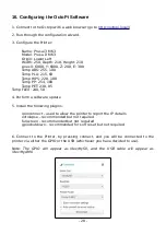
3. If you need the hard reset header. And it is not present installed, now is the time
to get out the soldering iron and fit it.
Note that you may find it difficult to solder in the ground pins due to the thermal
mass of the ground plane. If this is just for the reset header, you can use a ground
connection on the expansion header, and the reset header ground pin need not be
soldered.
- 14 -


