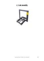


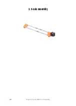
2. Y-axis assembly
Original Prusa i3 MK3S+ kit assembly
25
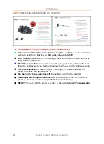
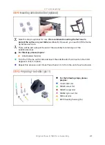
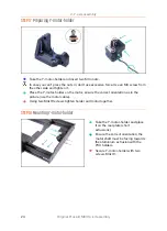
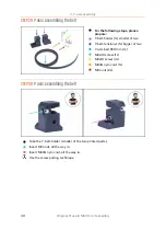
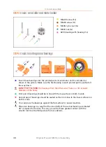
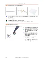
STEP 19
Y-axis: Y-carriage
For the following steps, please prepare:
Y-carriage (1x)
Linear bearing (3x)
Bearing clip (3x)
M3nN nyloc nut (6x)
M3x12 screw (6x)
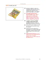
The printer's package contains a lubricant, which is intended for maintenance
.
No need to use it now the bearings are lubricated. There is a dedicated online
manual on how to clean the printer and apply the lubricant. See
help.prusa3d.com/maintenance-tips
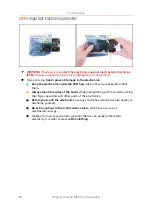
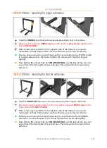
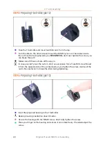
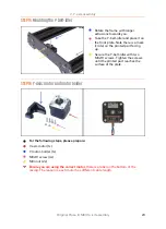
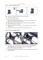
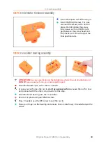
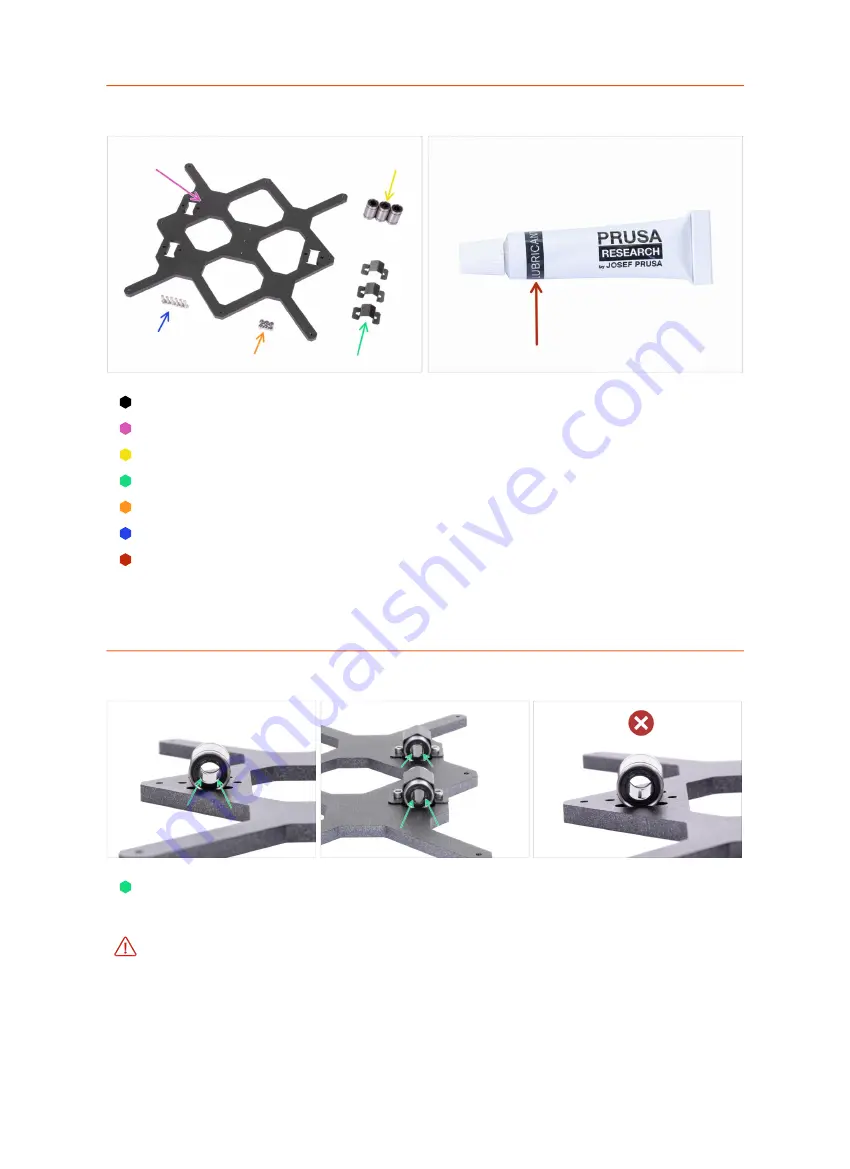
STEP 20
Correct bearing orientation
The correct orientation
: When placing bearings onto the Y-carriage,
make sure
that they are oriented as shown
in both pictures. The tracks (rows of balls) have to
be on the sides.
The incorrect orientation
:
Avoid placing the bearing like in the last picture!
This
orientation with a single row of balls in the center of the hole will later
increase the
wear of the smooth rod
, possibly creating a groove in it.
Summary of Contents for i3 MK3S+
Page 6: ...6 ...
Page 7: ...Original Prusa i3 MK3S kit assembly 7 1 Introduction ...
Page 15: ...Original Prusa i3 MK3S kit assembly 15 2 Y axis assembly ...
Page 36: ...36 Original Prusa i3 MK3S kit assembly 3 X axis assembly ...
Page 44: ...44 Original Prusa i3 MK3S kit assembly 4 Z axis assembly ...
Page 51: ...Original Prusa i3 MK3S kit assembly 51 5 E axis assembly ...
Page 88: ...88 Original Prusa i3 MK3S kit assembly 6 LCD assembly ...
Page 94: ...94 Original Prusa i3 MK3S kit assembly 7 Heatbed PSU assembly ...
Page 108: ...108 Original Prusa i3 MK3S kit assembly 8 Electronics assembly ...
Page 132: ...132 Original Prusa i3 MK3S kit assembly 9 Preflight check ...
Page 137: ...137 Notes ...
Page 138: ...138 ...
Page 139: ...139 Notes ...
Page 140: ...140 ...
Page 141: ...141 Notes ...
Page 142: ...142 ...
Page 143: ...143 Notes ...
Page 144: ...144 ...