


Building your MINI+
10
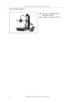
Original Prusa MINI+ semi-assembled
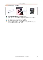
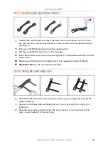
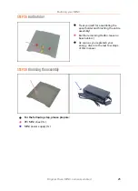
STEP 9
Foam pads installation
Peel the protective film from all pads. Be careful, there is glue (adhesive) applied on
the pad.
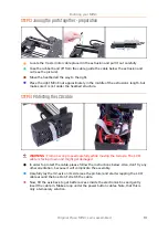
Lay the XZ-axis carefully on its side and the glue the first foam pad into the groove
on the bottom side of the electronics box.
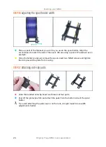
Rotate the Y-axis so that the heatbed is facing down. Put a soft pad or cloth
underneath it to prevent scratches.
Glue four foam pads onto the ends of the frame's aluminium extrusions, like in the
picture. Mind the correct orientation.
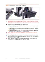
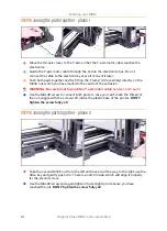
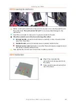
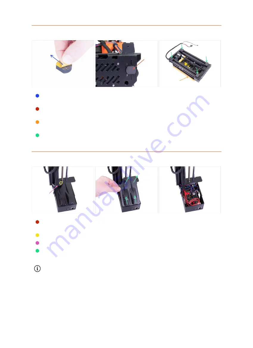
STEP 10
Opening the box with the electronics
Make sure that the Z-axis is in the upper position. If not, using your fingers turn the
leadscrew and move the Z-axis up.
Release and remove the M3 screw on the box with the electronics.
Remove the printed cable cover.
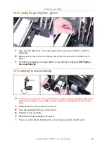
Lift the electronics cover slightly. Before you remove it completely, pull it first
towards the vertical aluminium extrusion to release both pins from the slots (holes
on older design).
Keep the box opened, we need to connect multiple cables throughout this manual.
Summary of Contents for MINI+
Page 2: ...2 ...
Page 3: ...Original Prusa MINI semi assembled 3 Manual changelog MINI semi assembly ...
Page 5: ...Original Prusa MINI semi assembled 5 Building your MINI ...
Page 27: ...27 Notes ...
Page 28: ...28 ...
Page 29: ...29 Notes ...
Page 30: ...30 ...
Page 31: ...31 Notes ...
Page 32: ...32 ...


