


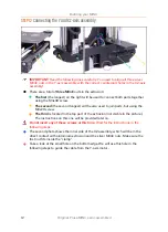


Building your MINI+
8
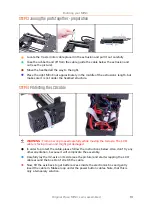
Original Prusa MINI+ semi-assembled
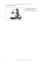
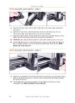
STEP 5
We are here for you!
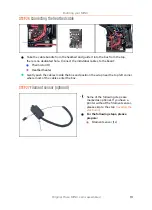
Lost in the instructions, missing a screw or dealing with a damaged printed part?
Let us know!
You can contact us using the following channels:
In the online version, use comments under each step.
Use our 24/7 live chat at
Write an email to
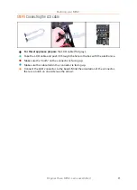
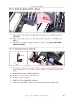
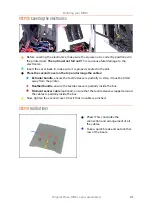
STEP 6
XYZ-axes parts preparation
For the following steps, please prepare:
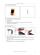
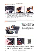
XZ-axis assembly
M3x40 screw (1x)
M3x20 screw (1x)
M3x12 screw (1x)
Note the second M3x20 screw in the package, will be used later on.
The list continues in the next step...
Summary of Contents for MINI+
Page 2: ...2 ...
Page 3: ...Original Prusa MINI semi assembled 3 Manual changelog MINI semi assembly ...
Page 5: ...Original Prusa MINI semi assembled 5 Building your MINI ...
Page 27: ...27 Notes ...
Page 28: ...28 ...
Page 29: ...29 Notes ...
Page 30: ...30 ...
Page 31: ...31 Notes ...
Page 32: ...32 ...


