


4. Print head & Heatbed assembly
Original Prusa MINI+ kit assembly
83
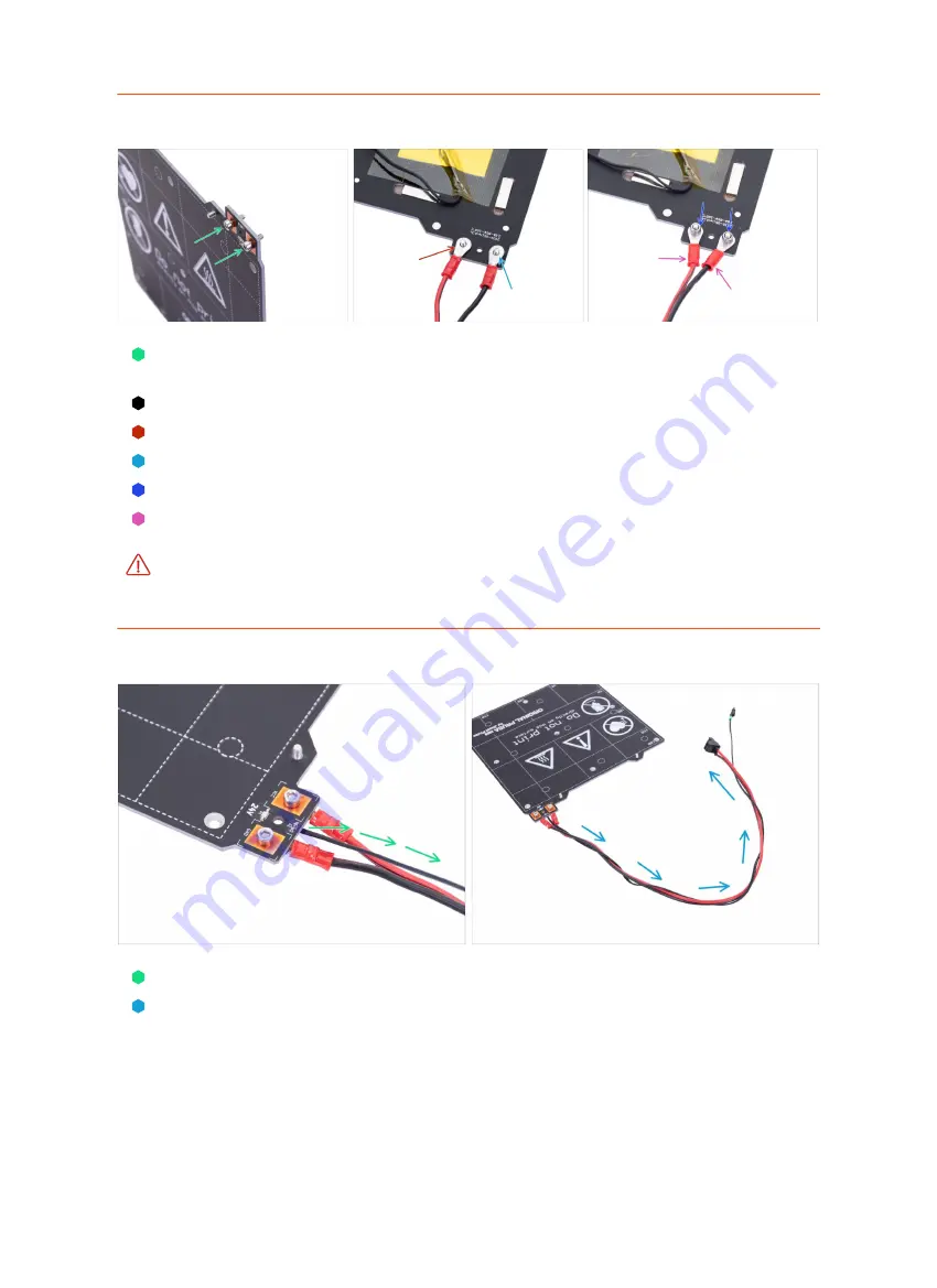
STEP 21
Assembling the heatbed
Insert two M3x8 screws to the heatbed. Screw heads must be on the top surface of
the heatbed.
Turn the heatbed bottom up and place it like in the picture.
Place the red wire (+) on the left screw.
Place the black wire (-) on the right screw.
Screw two M3nN nuts onto both screw and tighten.
The cable cover, which will be applied later requires the connectors to be slightly
inclined towards each other. Press them gently, but leave a gap between them.
Make sure the cables are connected properly and the screws are tightened.
Improper wiring can fatally damage the electronics.
STEP 22
Guiding the heatbed cables
Guide the black thermistor cable between the heatbed cables.
Wrap the thermistor cable a few times around the heatbed cables (see the photo).
Summary of Contents for Original Prusa MINI
Page 5: ...Original Prusa MINI kit assembly 5 1 Introduction ...
Page 14: ...14 Original Prusa MINI kit assembly 2 YZ axis assembly ...
Page 47: ...Original Prusa MINI kit assembly 47 3 X axis Extruder assembly ...
Page 73: ...Original Prusa MINI kit assembly 73 4 Print head Heatbed assembly ...
Page 87: ...Original Prusa MINI kit assembly 87 5 LCD assembly Electronics ...
Page 100: ...100 Original Prusa MINI kit assembly 6 Spool holder assembly ...
Page 105: ...Original Prusa MINI kit assembly 105 7 Preflight check ...
Page 109: ...109 Notes ...
Page 110: ...110 ...
Page 111: ...111 Notes ...
Page 112: ...112 ...
Page 113: ...113 Notes ...
Page 114: ...114 ...
Page 115: ...115 Notes ...
Page 116: ...116 ...


