


5. LCD assembly & Electronics
96
Original Prusa MINI+ kit assembly
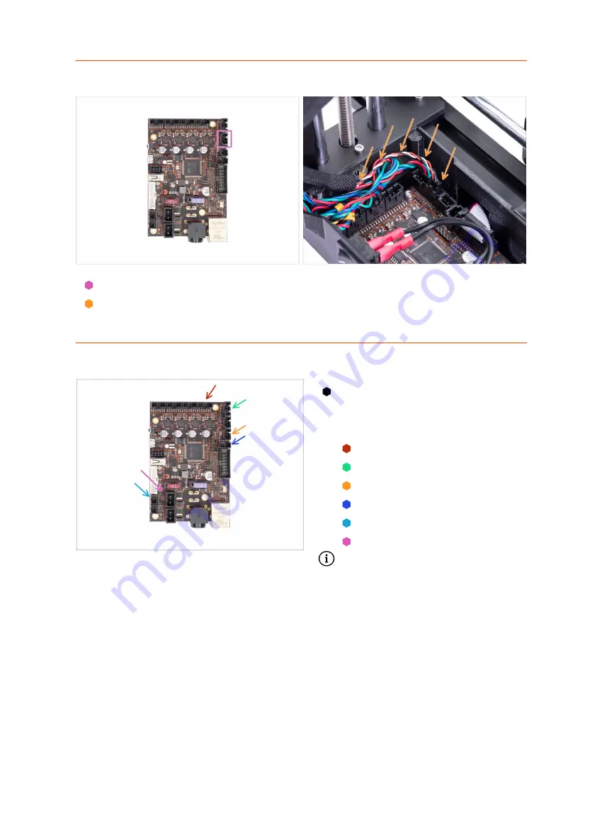
STEP 17
Connecting the filament sensor (optional)
Connect the filament sensor cable to the Buddy board.
Arrange the cable according to the picture. Keep in mind that the electronics cover
must fit into place.
STEP 18
Connecting the electronics
Let's connect the cables to the
electronics. Start from the top and
proceed "clockwise" according to
the instructions:
E-axis motor cable (labeled E)
SuperPINDA sensor cable
Print fan cable
Hotend fan cable
Hotend thermistor
Hotend cables
Continue in the next step...
Summary of Contents for Original Prusa MINI
Page 5: ...Original Prusa MINI kit assembly 5 1 Introduction ...
Page 14: ...14 Original Prusa MINI kit assembly 2 YZ axis assembly ...
Page 47: ...Original Prusa MINI kit assembly 47 3 X axis Extruder assembly ...
Page 73: ...Original Prusa MINI kit assembly 73 4 Print head Heatbed assembly ...
Page 87: ...Original Prusa MINI kit assembly 87 5 LCD assembly Electronics ...
Page 100: ...100 Original Prusa MINI kit assembly 6 Spool holder assembly ...
Page 105: ...Original Prusa MINI kit assembly 105 7 Preflight check ...
Page 109: ...109 Notes ...
Page 110: ...110 ...
Page 111: ...111 Notes ...
Page 112: ...112 ...
Page 113: ...113 Notes ...
Page 114: ...114 ...
Page 115: ...115 Notes ...
Page 116: ...116 ...


