


PS Engineering Inc. ®
PAR200A Audio Selector Panel, COM radio Controller and Intercom System
Installation and Operator’s Manual
200-228-0200
Page 2-8
Rev. 4, DEC. 2017
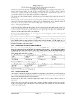
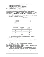
Unswitched
Input
Hear in
Fail Safe
Hear in
Crew Headset
Gain
1
Yes
Yes
1:1(fixed)
2
No
Yes
1:1(fixed)
3
No
Yes
Adjustable
4
No
Yes
1:1(fixed)
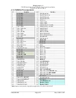
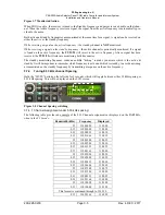
Table 2-4 Unswitched input table
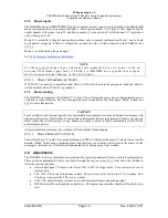
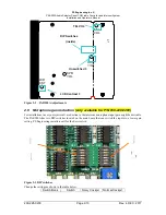
J1, pins 31, 29 and J2 pin 15 are unswitched, unmuted inputs # 1, 3 and 4, respectively. These inputs are
presented to the pilot and copilot regardless of the audio configuration, and will always mute the entertain-
ment inputs. These 510Ω inputs can be used for altimeter DH audio, GPS waypoint audio, autopilot discon-
nect tones, or any other critical audio signal.
The audio low for unswitched #4 (J2, pin 15) should be connected to a convenient audio low. However, this
should NOT be connected to Music Low.
Unswitched #1 is presented to the pilot headphone in fail-safe (off) mode.
NOTE
Inputs 1, 2 and 4 are fixed (1:1), and any audio level adjustments must be made at the input source. Unswitched #3 has a
variable adjustment control located on the bottom side of the unit. This control allows you to control the volume level of
that unswitched input from 50% to 200% of the input level. Refer to Adjustments section.
2.7 Intercom wiring
See Appendix C and D for intercom connection configurations. It is critical to the proper operation of this
system to have this connector wiring made in accordance with these diagrams. Use 2- and 3-conductor, MIL-
spec cable as shown. Connect the shields at the audio panel end only, and tie to the audio low inputs as shown.
NOTE
The system harness can be custom made by PS Engineering, Inc. Simply call the factory or
www.ps-engi-
neering.com
to obtain a wire harness work sheet. The harness will be made to your specifications and fully
functionally tested. Harness can be ordered with jack, or without the intercom jacks installed, for easier wire
routing through the aircraft.
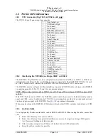
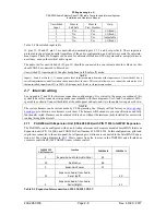
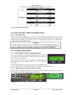
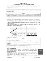
2.7.1
PAR200A with Expansion Unit (050-228-0202) with P/N 11636 IntelliPAX Expansion
The PAR200A can be configured with as an 8-station intercom with a remote mounted IntelliPAX Intercom
Expansion unit (P/N 11636R), and PAR200A Part Number 050-228-0202. In this configuration, pilot and
copilot are connected to the audio panel, but all passengers’ stations are connected to the IntelliPAX Expan-
sion unit. See wiring diagram in
§8.1
. Music comes from the sources in the PAR200A and all intercom
volume is controlled by the PAR200A inner volume control.
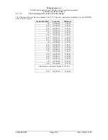
11636R EXP
UNIT Connector
Function
PAR200A J2
PAR200A J1
3
Expansion Audio to Audio Panel
35
14
Audio Low
36
1
Expansion Power
37
15
Expansion Audio from Audio
Panel (Left)
40
2
Expansion Audio from Audio
Panel (Right)
41
Table 2-5 Expansion Interconnections, 050-228-0202 ONLY