


PS Engineering Inc. ®
PAR200A Audio Selector Panel, COM radio Controller and Intercom System
Installation and Operator’s Manual
200-228-0200
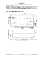
Appendix D
Rev. 2, Sept 2015
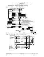
Appendix C – J1 Connector Interconnect
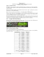
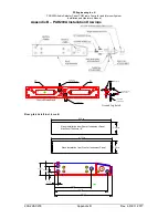
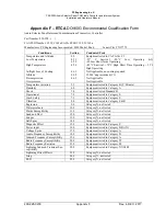
Figure 7-1 J1 connections, TY91/92(L)-05 as COM 2
Com 1 Audio Hi
Com 1 Mic Key
Com 1 Audio Lo
COM 1
Communications
Transceiver
COM 2
Communications
Transceiver
(TY91/TY92 -05)
Nav 1 Audio Hi
Nav 1 Audio Lo
VHF Nav 1
Nav 2 Audio Hi
Nav 2 Audio Lo
VHF Nav 2
Unswitc hed I nput #1 Hi
Unswitc hed Audio Lo
Unswitched Audio #1
Unswitc hed I nput #2 Hi
Unswitc hed Audio Lo
Unswitched Audio #2
Pilot Mic Audio Hi
Pilot Mic PTT
Pilot Mic Lo
9
10
11
12
Com 1 Mic Audio Hi
Com 2 Audio Hi
Com 2 Mic Key
Com 2 Audio Lo
13
14
15
30
Com 2 Mic Audio Hi
17
18
19
20
17
29
31
32
44
43
Notes:
1. All AUDIO shields should be grounded at audio panel only. Other end remains floating.
Serial Data should be grounded at BOTH ends.
2. PAR200 Power, and Ground wires shall be #22 gage wire
TY91/TY92 Power and Ground shall be 20 AWG minimum
Lighting and TY91/92 interface #22 AWG, other wires minimum #24 AWG
3. All mic and headphone jacks must be isolated from ground.
4. All shielded wires must be MIL 22750 or 27500.
5. Unswitched inputs are always presented to
crew headphones, regardless of SPR switch or PTT.
Unswitched #3 is adjustable
6. TY91 or TY92 interfaced as COM 2.
All connections for TY91/92(L) Radio shown for convenience.
7. Connect J1 25 to J1 26 for TY91/92 as COM 2.
Pilot PTT
PAR 200A C onnector, J1 (S ub-D 44-pin, male on tray)
Unswitc hed I nput #3 Hi
Unswitc hed Audio Lo
Unswitched Audio #3
29
S
e
e
N
o
te
5
Pass . Phones (R)
Pass Phones (L)
Pass . Phones Lo
Pass . 1 Phones Jack
Pass . 2 Phones J ac k
22
RS232 RX
RS232 TX
2
1
23
15
6
5
J2
See Note 2, 6
12
30
42
Radi o On
Radi o Power
Radi o G round
13
12
9
19
24
25
Airframe Ground
5A
Airfr ame G round
25
26
See Note 7
33
34
35
41
40
42
TY91L 11-33
TY92 18-33
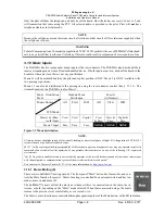
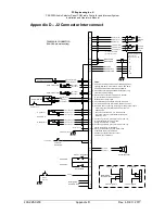
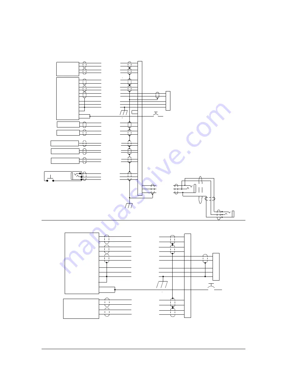
Figure 7-2 PAR200A Using TY91/92(L) as COM1 or stand alone
Com 1 Audio Hi
Com 1 Mic Key
Com 1 Audio Lo
COM 2
Communications
Transceiver
COM 1
Communications
Transceiver
(TY91/92)
9
10
11
12
Com 1 Mic Audio Hi
Com 2 Audio Hi
Com 2 Mic Key
Com 2 Audio Lo
13
14
15
30
Com 2 Mic Audio Hi
17
29
12
30
42
RS232 RX
RS232 TX
2
1
23
15
6
5
Radio On
Radio Power
Radio Ground
13
12
9
19
24
25
J2
J1
25
26
NOTE: DO NOT CONNECT
J1-25 to J1-26
to set TY91/92L as COM 1
N/C
N/C