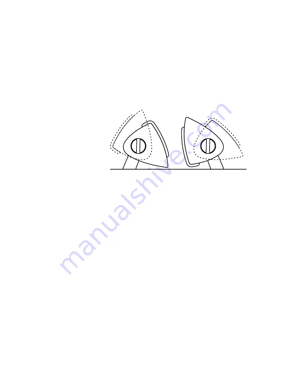
caps. This assures that the system stays put at any angle that you set it. Also note
that the mounting bracket ends have slots that allow over an inch of in/out
adjustment. This range can be used to tilt the system slightly when on wall and also
to adjust the space between the system and the wall. Most likely the installer will
hang the system on the wall with the brackets loose, connect the wires and then
push the system close to the wall and tighten the knobs.
The question of orientation may arise. That is, when mounted vertically, which side
of the system should be inside and which should be outside? Acoustically the
response is quite symmetrical so it becomes a matter of visual preference. The
system is typically mounted with the exposed cabinet edge to the inside (towards the
Plasma set) because
when angled inward the
system sets nearer the
wall.
When the VS300 is wall
mounted you may prefer
to tilt the speakers
towards ear level by
l o o s e n i n g t h e
a t t a c h m e n t s c r e w s
slightly and pulling one
end or the other forward.
This shouldn't be required for acoustical reasons but can help align the system with
a TV that angles slightly downward, for cosmetic reasons. A slot in the wall
attachment bracket is long enough for useful angle adjustment.
Table top mounting with the optional VisionSound Base Kit
You may be using the VS300’s next to a table top mounted TV. If so it may be
preferable to stand them upright on the table rather than to wall mount them. We
have provided for this with the optional VisionSound Base Kit. (One pair of bases per
kit) Each kit includes two cast aluminum bases, a left and right spacer and
replacement (sans knobs) top caps. The bases are nicely weighted and have rubber
feet to keep from marring furniture.
To attach them you should first remove the two knobs and the wall bracket. Then
both end caps need to come off. Although the end caps are snugly attached a firm
grasp and steady pull (wiggle side to side) will remove them. Resist the temptation to
pry them off with a screwdriver which would certainly mar the cabinet. Use a Philips
screwdriver to remove the 4 screws from one end of either system. Note that you are
turning “centers” into “lefts” and “rights” and so you need to remove the screws from
one end of one system and the opposite end of the other. Add the appropriate
adaptor plate (the plastic piece approximately ¾” thick) and reattach and snug the
screws. The flat side of the spacer will attach to the VS300. The curved side is a mate
to the aluminum base. The cast base then attaches via 3 hex key type (key included)
screws. Finally, attach the new end caps. Note that you won’t be re-using the knobs
so the new end caps delete the knob hole and also the unused bracket slot around
back for a clean appearance.
9


