13/22
NT 1401-X00 10 18 B200 Flow Control e
The non balancing of the drive shafts can lead to
mechanical ruptures that are susceptible of causing
important property damage and/or serious injuries.
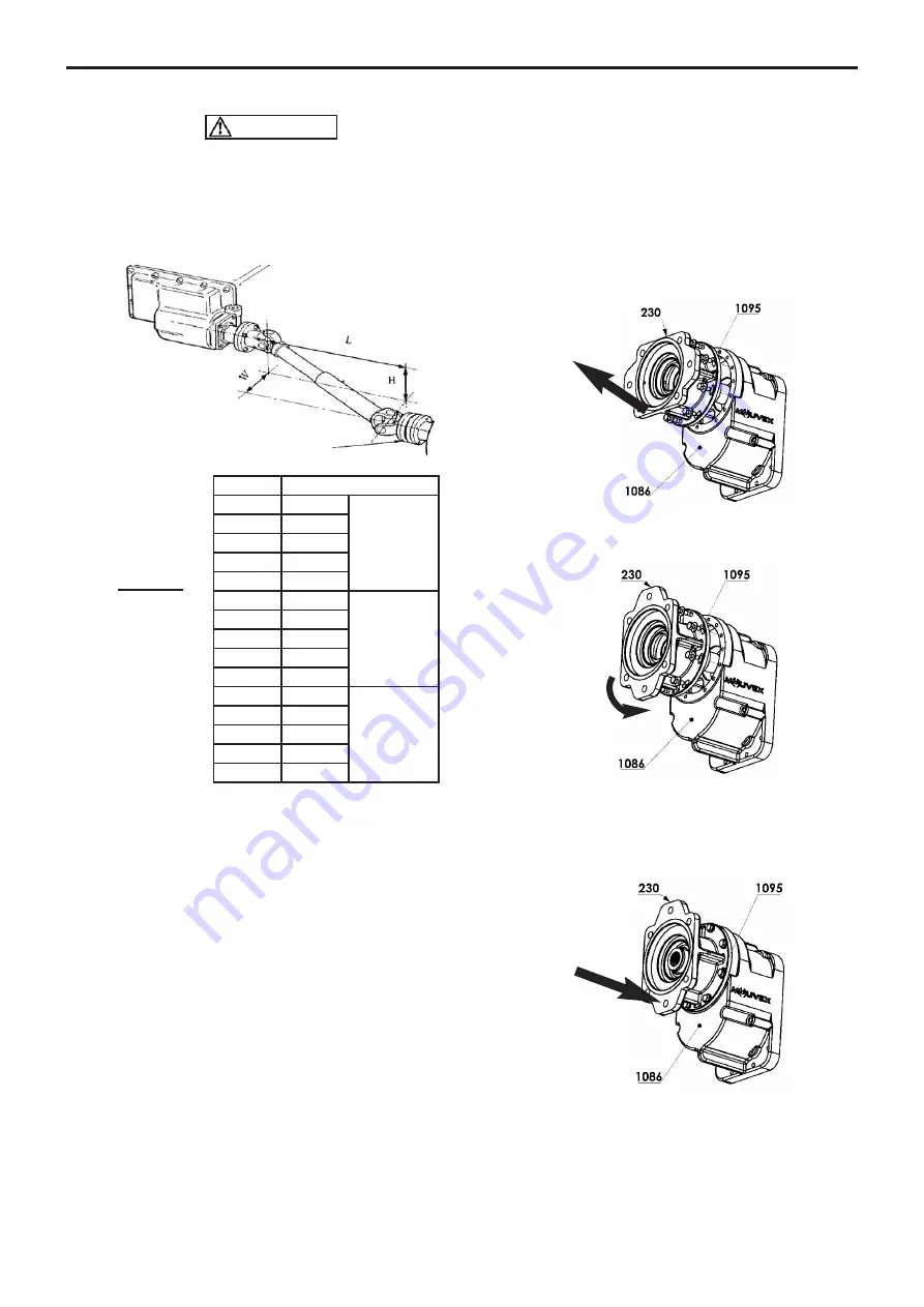
• The drive shaft and compressor shaft MUST be parallel
within 1° and have a maximum of 10°compound misali-
gnment. See Table :
• Universal joints MUST be in phase, with the drive shaft
slip joint at mid-position. Use an even number of uni-
versal joints.
• Make sure that the compressor rotates in the direction
of the arrow on the body.
The B200 compressors fitted with a check valve can
withstand a short operating time (less than 30
seconds) in the opposite direction, as required for
checking the rotation direction.
NOTICE :
Prolonged operation in a direction different from the
direction indicated on the drawing below may cause
serious damage to the compressor and would cancel the
warranty.
3.3 B200 HY with hydraulic motor
The B200 HY compressors have a female splined shaft
ANSI B92-1a that allows to flange directly on hydraulic
motor epuipped with a shaft 13T 718 SAE 16/32 and a
mounting flange SAE B 2 or 4 holes.
3.3.1 Hydraulic motor assembly
It is possible to change the orientation of the lantern
230
,
taking care to proceed as follows :
• Loosen and remove the 8 screws
1095
.
• Rotate the lantern
230
so as to offset the ports and
move them over the set of tapped holes on casing
1086
that approach the desired position.
• Make sure that at least one of the 2 collectors is loca-
ted in the lower part of the lantern
230
, otherwise turn
the lantern 230 by 180°.
• Engage the lantern
230
.
• Tighten the 8 screws
1095
.
A
Universal joint angle
0,017
1°
VERY GOOD
0,035
2°
0,052
3°
0,070
4°
0,087
5°
0,105
6°
GOOD
0,125
7°
0,141
8°
0,158
9°
0,176
10°
0,194
11°
LIMIT
VALUES
0,213
12°
0,231
13°
0,249
14°
0,268
15°
_________
A =
√
H² + W²
L
If H = Zero, A = W / L
If W = Zero, A = H / L
CAUTION
3. INSTALLATION (continued)


