16/22
NT 1401-X00 10 18 B200 Flow Control e
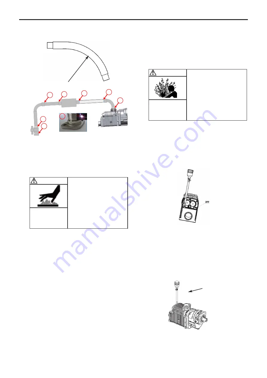
Top view
Installation rules : Discharge line
All the connections must be welded and be the object
of a waterproof quality control.
During installation, position a pressure gage on the com-
pressor output, so as to measure the operating pressure.
The measurement should be done at the discharge flange
level and should not exceed 2,5 bar over the allowable
operating range of the compressor.
It is mandatory to protect the compressor with the Check
relief valve supplied by MOUVEX. The check valve pre-
vents any air from returning in the compressor when it is
no longer in operation.
The safety valve protects the compressor against possi-
ble overpressure. The maximum set point of the valve is
2,5 bar.
If there is a drop in pressure between the pres-
sure relief valve and the compressor, reduce the pres-
sure relief valve setting by the value of the pressure
drop.
It is the installor responsability to check that the
relief valve is compliant with the compressor performance
for the application speed.
The compressor is delivered with a check and relief valve
allowing 3 settings capabilities : 2 bar, 2,3 bar or 2,5 bar.
It will have to be selected depending of the installation limits
and by making sure the maximum pressure of 2,5 bar of
the compressor is never exceeded. Be careful in particular
with the pressure drop located between the check relief
valve and the compressor especially if an air cooler and
a silencer are used.
It is forbidden to insert a damping valve in the pipe lin-
king the compressor to the tank hose connector in order
to avoid any risk of water entering.
Ensure that ALL components are capable of operation at
the maximum system pressure limits and that all vessels
are adequately protected by SEPARATE relief valves.
3.4.3 Oil breather
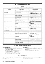
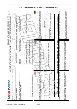
Compressor B200 is fitted with an oil breather which is
mounted on a hose for easier installation.
In case of the inclination of the compressor, it is essen-
tial to position the breather on the highest tapped hole.
Invert the positions of the oil gage
399
and the breather
assembly, as appropriate.
Position the breather plug in a clear area, to avoid any oil
condensation.
Do not crush the hose when positioning the breather, so
as to allow any oil vapors to be evacuated.
The hose mustn’t be shortened,, keeps imperatively its
original length.
The breather must be placed above the compressor,
preferably with the connecting hose running up towards
the breather.
1
1
1
1
1
1
1
1
CRV
Option
silencer
Hose (B200PF)
Oil breather
}
R mini 50 cm
WARNING
FAILURE TO INSTALL ADEQUATELY
SIZED PRESSURE RELIEF VALVE(S)
CAN CAUSE PROPERTY DAMAGE,
PERSONAL INJURY OR DEATH.
Hazardous pressure
can cause
personal injury
or property damage.
CAUTION
OPERATING A COMPRESSOR ABOVE
ITS MAXIMUM OPERATING PRESSURE
CAN CAUSE SUBSTANTIAL PROPERTY
DAMAGE OR SERIOUS BODILY INJU-
RIES.
Extreme heat can
cause injury or
property damage.
3. INSTALLATION (continued)


