background image

19/22

NT 1401-X00 10 18 B200 Flow Control  e

5. MAINTENANCE (continued)

5.3 Inlet shaft replacement

The B200 PF inlet shaft has a groove that breaks the
shaft in case of excess torque, as required to protect the
gear box and the PTO.

Before replacing the inlet shaft, it is essential to make sure
that the compressor is not damaged :

• Loosen and remove the 8 screws

1095

.

• Remove the wheel, complete with the remaining part

of the shaft.

• Rotate the wheel 

manually and check that it can

rotate freely and without any hard point over a com-
plete rotation.

• Inspect the screws on the discharge part and make

sure that there are not any marks of contact between
the screws, or due to the presence of any foreign
bodies.

The compressor is to replace if :

• wheel 

6

does not rotate.

• wheel 

6

cannot rotate easily.

• marks can be seen on the screws.

• Engage the bearing of shaft kit 

1071

in the housing of

casing

1086

.

• Check the state of the lip seals

1089 

and the O’ring

40

. Make sure that they are not damaged.

• Engage the lantern

230

in the desired position.

• Tighten the 8 screws 

1095

.

For the installation of the compressor on the power take-
off, refer to § DIRECT INSTALLATION ON B200 PF TRUCK

POWER TAKE-OFF.

Screws 

1095

must be :

• equipped with their lock washers, notches on the

side of the screw head,

• sealed with Loctite

®

* thread locking 243 or equivalent,

• tightened at 13 Nm.

5.4 Warranty claims

The compressor oil is considered as wear part.

No failure connected with wear part damage will be
accepted under warranty conditions.

The following situations will void warranty for all compo-
nents of the compressor :

• Installation not in accordance with the CL 1401-001

Control check list installation B200 FC.

• No MOUVEX Check relief valve.

• Tampering with the setting of the relief valve.

• Presence of foreign body inside the compressor body.

• Traces of damage representative of abnormal use of

the compressor.

• Use of non genuine parts.

• If the compressor is repaired by a repairer who is not

a MOUVEX-approved repairer.

• Construction of the package not validated by our

Design Office.

• Use of an oil other than BSC2.

• Presence of a dumping valve on the pipe linking the

compressor to the tank hose connector.

• Motor management not fixed, allowing the operator a

using outside the working range.

Before returning your equipment to the factory, you must
first obtain an Equipment return approval (RMA) from our
After Sales Department.

A Compressors form information shall be filled by the
installer or distributor and send to MOUVEX in order to
claim for a warranty.

WARNING

CAUTION

Loctite

®

is a registered trademark.

Summary of Contents for Mouvex B200 Flow Control

Page 1: ...e des Isles F 89000 AUXERRE FRANCE Tel 33 0 3 86 49 86 30 Fax 33 0 3 86 49 87 17 contact mouvex com www mouvex com WARRANTY B200 Flow Control compressors are covered 36 months by warranty within the l...

Page 2: ...ive shaft 12 3 3 B200 HY with hydraulic motor 13 3 4 Piping 14 4 USE OF COMPRESSOR 17 4 1 Lubricant recommendations 17 4 2 Filling of lubricant 17 4 3 Operation 17 5 MAINTENANCE 18 5 1 Maintenance sch...

Page 3: ...IQUEFIED GASSES OR POWDERS THOUGH THE COMPRESSOR TO DO SO WOULD VOID THE WARRANTY LIFTING POINTS The compressor can be picked up from underneath to be transported Discharge flanges threads can be used...

Page 4: ...Swivel cover Drain plugs Breather plug Plug speed measure Oil gauge Oil fill plug Flange 1 5 BSP Splines B8x32x36 DIN 5462 2 holes M10x15 2x 3 holes M10x15 Direction of rotation MALE SPLINED SHAFT VER...

Page 5: ...ivel cover Drain plugs Breather plug Plug speed measure Oil gauge Oil fill plug Flange 1 5 BSP 2 holes M10x15 2x 3 holes M10x15 Direction of rotation B200 12R 10L HY Splines ANSI B92 1a 7 8 SAE_16 32...

Page 6: ...6 22 NT 1401 X00 10 18 B200 Flow Control e 1 OVERALL DIMENSIONS continued SILENCER DN 40 CHECK AND RELIEF VALVE...

Page 7: ...seals do not enter in contact with the shaft and are not subject to wear Thanks to their rugged design B200 compressors have a long service life B200 compressors need very limited maintenance which re...

Page 8: ...slightly based on the following parameters Dimensional dispersion associated to the tolerances of components When the CRV is cold it generates a greater pressu re of 0 15 bar The opening of valves nat...

Page 9: ...Flow measurement ISO 5162 2 Mesure bruit Noise measurement 1m de la CRV 1 5 m du compresseur 1 m from the CRV 1 m from the compressor 81 0 83 0 85 0 87 0 89 0 91 0 93 0 95 0 97 0 99 0 101 0 0 20 40 60...

Page 10: ...and operating conditions The use of the discharge flexible supplied by MOUVEX fitted in accordance with the B200 Instructions The use of the fixation kit supplied by MOUVEX fitted in accordance with t...

Page 11: ...tachometer of the Multimetrix RPM82 type is perfectly well suited for measuring the speed on the screws of the B200 compressor Since the male and female screws do not rotate at the same speed refer t...

Page 12: ...cks Compressors B200 12R PS and B200 10L PS must be protected by a 400 Nm torque limiter in order to protect the truck s transmission if the compressor is jammed MOUVEX may not be held liable for any...

Page 13: ...to the compressor and would cancel the warranty 3 3 B200 HY with hydraulic motor The B200 HY compressors have a female splined shaft ANSI B92 1a that allows to flange directly on hydraulic motor epui...

Page 14: ...ging the Compressor This is particularly sensitive for the B200 PF which is equipped with a shaft groove It is in particular to ensure that the parameter TRANSMISSION INPUT SPEED N 10 520 on MERCEDES...

Page 15: ...supplied must be equipped with its gasket screw tightened at 44 Nm Piping MUST be at least as large as the compressor suction and discharge connections All the connections located between the compres...

Page 16: ...ted between the check relief valve and the compressor especially if an air cooler and a silencer are used It is forbidden to insert a damping valve in the pipe lin king the compressor to the tank hose...

Page 17: ...3 3 Start up procedure for manual gear box Start the engine and run with standard speed Depress clutch and engage the PTO Release the clutch SLOWLY Set engine speed to give the correct compressor spee...

Page 18: ...compressor system piping and components Clean or repair as necessary 4 Check power transmission line 5 Check the air filter restriction indicator When the indica tor turns red replace the filter cartr...

Page 19: ...Screws 1095 must be equipped with their lock washers notches on the side of the screw head sealed with Loctite thread locking 243 or equivalent tightened at 13 Nm 5 4 Warranty claims The compressor oi...

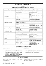
Page 20: ...g point 3 Abnormal high temperature Air filter clogged To clean the cartridge or to replace it Air pressure too much high To see problems 1 2 Outside temperature too much high To respect the maximum e...

Page 21: ...Belt drive system PTO ratio Package air cooler Package RTI Product transfered Air connection on truck chimney Direct air connection Flexible pipe between filter and compressor Inox pipe between filter...

Page 22: ...ungen bezogen auf mechanische und elektrische Risiken die f r rotierende Maschinen gelten NF EN 809 2009 NF EN 1672 2 2009 NF EN ISO 13857 2008 NF EN 12162 2009 ATEX Richtlinie 2014 34 EU 26 Feb 2014...

Reviews: